Entry And Start System Certification Ecu Power Source Circuit
DESCRIPTION
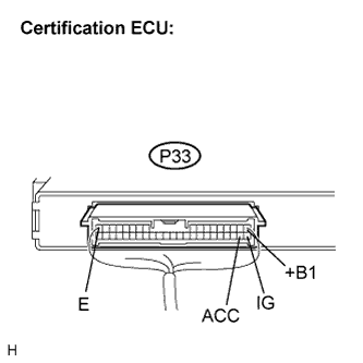
WIRING DIAGRAM
INSPECTION PROCEDURE
CHECK HARNESS AND CONNECTOR (POWER SOURCE CIRCUIT)
ENTRY AND START SYSTEM - Certification ECU Power Source Circuit |
DESCRIPTION
This is the power source circuit of the certification ECU.The certification ECU controls the following:- Electrical key verification confirmation
- Cabin and door oscillator control
- Entry door LOCK / UNLOCK request to the main body ECU RH
- Steering LOCK / UNLOCK request
- Immobilizer SET / UNSET request to the ID code box
WIRING DIAGRAM
INSPECTION PROCEDURE
| 1.CHECK HARNESS AND CONNECTOR (POWER SOURCE CIRCUIT) |
Disconnect the P33 certification ECU connector.
Measure the voltage according to the value(s) in the table below.
- Standard voltage:
Tester Connection (Symbols)
| Condition
| Specified Condition
|
P33-1 (+B1) - Body ground
| Always
| 10 to 14 V
|
P33-18 (IG) - Body ground
| Engine switch OFF
| Below 1 V
|
Engine switch ON (IG)
| 10 to 14 V
|
P33-19 (ACC) - Body ground
| Engine switch OFF
| Below 1 V
|
Engine switch ON (ACC)
| 10 to 14 V
|
Measure the resistance according to the value(s) in the table below.
- Standard resistance:
Tester Connection (Symbols)
| Condition
| Specified Condition
|
P33-17 (E) - Body ground
| Always
| Below 1 Ω
|
| | REPAIR OR REPLACE HARNESS OR CONNECTOR |
|
|
| OK |
|
|
|
| PROCEED TO NEXT CIRCUIT INSPECTION SHOWN IN PROBLEM SYMPTOMS TABLE |
|