Dtc B1243 Gsw Terminal Circuit Malfunction
DESCRIPTION
WIRING DIAGRAM
INSPECTION PROCEDURE
CHECK HARNESS AND CONNECTOR (CENTER AIRBAG SENSOR - MAIN BODY ECU RH)
INSPECT COWL SIDE JUNCTION BLOCK RH (MAIN BODY ECU RH)
DTC B1243 GSW Terminal Circuit Malfunction |
DESCRIPTION
If the collision door lock release function does not operate normally, or an open or short in the GWS input circuit of the main body ECU RH (cowl side J/B RH) is detected, DTC B1243 will be output.- HINT:
- If DTC B1243 is output, the speed-sensitive automatic door lock function, shift-linked automatic door unlock function, and collision door lock release function will be prohibited.
DTC No.
| DTC Detection Condition
| Trouble Area
|
B1243
| A malfunction occurs in the GWS input circuit of the main body ECU RH (cowl side J/B RH).
| - Main body ECU RH (Cowl side J/B RH)
- Center airbag sensor
- Wire harness
|
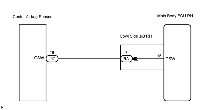
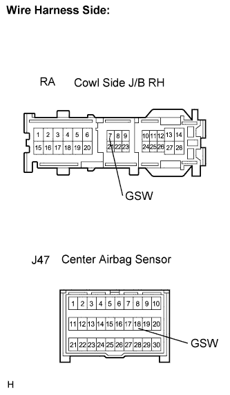
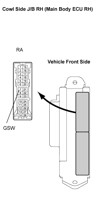
WIRING DIAGRAM
INSPECTION PROCEDURE
| 1.CHECK HARNESS AND CONNECTOR (CENTER AIRBAG SENSOR - MAIN BODY ECU RH) |
Connect the negative (-) terminal cable to the battery, and wait for at least 90 seconds.
Disconnect the center airbag sensor J47 and J/B RA connectors.
Measure the resistance according to the value(s) in the table below.
- Standard resistance:
Tester Connection
(Symbols)
| Condition
| Specified Condition
|
J47-18 (GSW) - RA-7 (GSW)
| Always
| Below 1 Ω
|
RA-7 (GSW) - Body ground
| Always
| 10 kΩ or higher
|
| | REPAIR OR REPLACE HARNESS OR CONNECTOR |
|
|
| 2.INSPECT COWL SIDE JUNCTION BLOCK RH (MAIN BODY ECU RH) |
Reconnect the J/B RA connector.
Turn the engine switch on (IG).
Measure the voltage according to the value(s) in the table below.
- Standard voltage:
Tester Connection
(Symbols)
| Condition
| Specified Condition
|
RA-7 (GSW) - Body ground
| Engine switch on (IG)
| 4.5 to 5.5 V
|
| | REPLACE COWL SIDE JUNCTION BLOCK RH |
|
|
| OK |
|
|
|
| REPLACE CENTER AIRBAG SENSOR |
|