Symbols (Terminal No.)
| Wiring Color
| Terminal Description
| Condition
| Specified Condition
|
J58-1 (B) - J58-20 (GND)
| Y - W-B
| Power source (Back-up)
| Always
| 10 to 14 V
|
J58-2 (MHTR) - J58-20 (GND)
| BR - W-B
| MIR/HTR relay signal
| Engine switch on (IG), REAR DEF switch: OFF
| 10 to 14 V
|
J58-2 (MHTR) - J58-20 (GND)
| BR - W-B
| MIR/HTR relay signal
| Engine switch on (IG), REAR DEF switch: ON
| Below 1 V
|
J58-3 (RDEF) - J58-20 (GND)
| B - W-B
| DEFOG relay signal
| Engine switch on (IG), FRONT DEF switch: OFF
| 10 to 14 V
|
J58-3 (RDEF) - J58-20 (GND)
| B - W-B
| DEFOG relay signal
| Engine switch on (IG), FRONT DEF switch: ON
| Below 1 V
|
*1 J58-4 (HTR2) - J58-20 (GND)
| LG - W-B
| GLW RLY2 relay signal
| Engine switch on (IG)
| 10 to 14 V
|
*1 J58-4 (HTR2) - J58-20 (GND)
| LG - W-B
| GLW RLY2 relay signal
| Engine switch on (IG)
Engine running at 850 rpm or more, Ambient temperature 0°C (32°F) or less, Engine coolant temperature 69°C (156°F) or less, Temperature switch: MAX HOT, Blower switch: LO
| Below 1 V
|
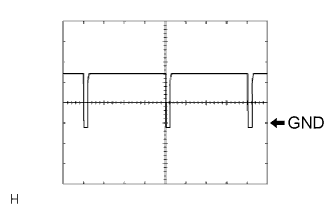
J58-5 (SOL+) - J58-20 (GND)
| G - W-B
| A/C compressor operation signal
| Engine switch on (IG), A/C switch: ON
| Pulse generation
(See waveform 1)
|
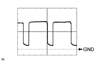
J58-11 (BLW) - J58-20 (GND)
| O - W-B
| Blower motor speed control signal
| Engine switch on (IG), Blower switch: ON
| Pulse generation
(See waveform 2)
|
J58-13 (PRE) - J58-38 (SG-2)
| V - P
| Pressure sensor signal
| Start engine, Operate A/C system, Refrigerant pressure: Abnormal pressure (more than 3,030 kPa (31.0 kgf/cm, 440 psi))
| 4.7 V or higher
|
J58-13 (PRE) - J58-38 (SG-2)
| V - P
| Pressure sensor signal
| Start engine, Operate A/C system, Refrigerant pressure: Abnormal pressure (less than 180 kPa (1.9 kgf/cm, 27 psi))
| Below 0.7 V
|
J58-13 (PRE) - J58-38 (SG-2)
| V - P
| Pressure sensor signal
| Start engine, Operate A/C system, Refrigerant pressure: Abnormal pressure (more than 3,030 kPa (31.0 kgf/cm, 440 psi) and less than 180 kPa (1.9 kgf/cm, 27 psi))
| 0.7 to 4.7 V
|
J58-14 (TSP) - J58-20 (GND)
| P - W-B
| Passenger side solar sensor signal
| Engine switch on (IG), Solar sensor subjected to electric light
| 0.8 to 4.3 V
|
J58-14 (TSP) - J58-20 (GND)
| P - W-B
| Passenger side solar sensor signal
| Engine switch on (IG), Solar sensor is covered with a cloth
| Below 0.8 V
|
J58-16 (TR) - J58-19 (SG-1)
| G - L
| Room temperature sensor signal
| Engine switch on (IG), Cabin temperature: 25°C (77°F)
| 1.6 to 1.8 V
|
J58-16 (TR) - J58-19 (SG-1)
| G - L
| Room temperature sensor signal
| Engine switch on (IG), Cabin temperature: 40°C (104°F)
| 0.8 to 1.0 V
|
J58-19 (SG-1) - Body ground
| L - Body ground
| Ground for room temperature sensor
| Always
| Below 1 V
|
J58-20 (GND) - Body ground
| W-B - Body ground
| Ground for main power supply
| Always
| Below 1 V
|
J58-21 (IG+) - J58-20 (GND)
| B - W-B
| Power source (IG)
| Engine switch on (IG)
| 10 to 14 V
|
J58-21 (IG+) - J58-20 (GND)
| B - W-B
| Power source (IG)
| Engine switch off
| Below 1 V
|
*1 J58-23 (HTR1) - J58-20 (GND)
| L - W-B
| GLW RLY1 relay signal
| Engine switch on (IG)
| 10 to 14 V
|
*1 J58-23 (HTR1) - J58-20 (GND)
| L - W-B
| GLW RLY1 relay signal
| Engine switch on (IG)
Engine running at 850 rpm or more, Ambient temperature 0°C (32°F) or less, Engine coolant temperature 69°C (156°F) or less, Temperature switch: MAX HOT, blower switch: LO
| Below 1 V
|
J58-26 (S5-2) - J58-38 (SG-2)
| W - P
| Power supply for pressure sensor
| Engine switch on (IG), A/C switch: ON
| 4.5 to 5.5 V
|
J58-26 (S5-2) - J58-38 (SG-2)
| W - P
| Power supply for pressure sensor
| Engine switch on (IG), A/C switch: OFF
| Below 1 V
|
J58-30 (MPX+) - J58-31 (MPX-)
| BR - BR
| Multiplex communication system
| Multiplex communication circuit
| -
|
*1 J58-33 (DGS1) - J58-39 (SG-6)
| R - Y
| Exhaust gas sensor signal (Nox)
| 30 seconds have elapsed after the engine switch is turned on (IG) and sensor is exposed to exhaust gas
| 1.0 to 4.5 V
|
*1 J58-34 (DGS) - J58-39 (SG-6)
| BR - Y
| Exhaust gas sensor signal (HC, CO)
| 30 seconds have elapsed after the engine switch is turned on (IG) and sensor is exposed to exhaust gas
| 1.0 to 4.5 V
|
J58-35 (TSD) - J58-20 (GND)
| LG - W-B
| Driver side solar sensor signal
| Engine switch on (IG), Solar sensor subjected to electric light
| 0.8 to 4.3 V
|
J58-35 (TSD) - J58-20 (GND)
| LG - W-B
| Driver side solar sensor signal
| Engine switch on (IG), Solar sensor is covered with a cloth
| Below 0.8 V
|
*2 J58-36 (TAM) - J58-37 (SG)
| SB - L
| Ambient temperature sensor signal
| Engine switch on (IG) at 25°C (77°F)
| 1.8 to 2.2 V
|
*2 J58-36 (TAM) - J58-37 (SG)
| SB - L
| Ambient temperature sensor signal
| Engine switch on (IG) at 40°C (104°F)
| 1.2 to 1.6 V
|
*2 J58-37 (SG) - Body ground
| L - Body ground
| Ground for ambient temperature sensor
| Always
| Below 1 V
|
J58-38 (SG-2) - Body ground
| P - Body ground
| Ground for pressure sensor
| Always
| Below 1 V
|
J58-39 (SG-6) - Body ground
| Y - Body ground
| Ground for exhaust gas sensor
| Always
| Below 1 V
|
e1- 2 (BUS G) - Body ground
| -
| Ground for BUS IC
| Always
| Below 1 V
|
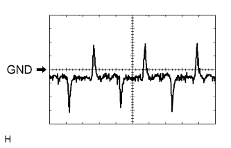
e1- 3 (BUS) - e1-2 (BUS G)
| -
| BUS IC control signal
| Engine switch off → on (IG)
| Pulse generation
|
e1-4 (B BUS) - e1-2 (BUS G)
| -
| Power supply for BUS IC
| Engine switch on (IG)
| 10 to 14 V
|
e1-4 (B BUS) - e1-2 (BUS G)
| -
| Power supply for BUS IC
| Engine switch off
| Below 1 V
|
e1-6 (TE) - e1-5 (SG)
| -
| Evaporator temperature sensor signal
| Engine switch on (IG), Evaporator temperature 0°C (32°F)
| 2.0 to 2.4 V
|
e1-6 (TE) - e1-5 (SG)
| -
| Evaporator temperature sensor signal
| Engine switch on (IG), Evaporator temperature 15°C (59°F)
| 1.4 to 1.8 V
|