Manifold Absolute Pressure Sensor -- On-Vehicle Inspection |
| 1. INSPECT ABSOLUTE PRESSURE SENSOR |
Inspect power source voltage.
Disconnect the absolute pressure sensor connector.
Turn the engine switch on (IG).
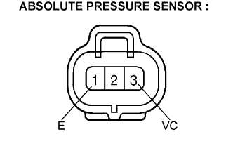
Using a voltmeter, measure the voltage between terminals 3 (VC) and 1 (E) of the wiring harness side connector.
- Voltage:
- 4.75 to 5.25 V
Turn the engine switch off.
Reconnect the absolute pressure sensor connector.
 |
Inspect sensor output.
Turn the engine switch on (IG).
Disconnect the vacuum hose from the absolute pressure sensor.
Connect a voltmeter to terminals PIM (E12-28) and E2 (E13-28) of the ECM and measure the output voltage of the sensor at atmospheric pressure. Record this voltage reading.
- HINT:
- This step allows a base voltage value (at atmospheric pressure) to be determined. This base value will be used to determine the voltage change due to different pressures or vacuum being applied to the sensor.
Apply vacuum to the absolute pressure sensor as shown in the table below.
Measure the drop in voltage from the base value that was recorded in step 3.
Compare these results to the specified voltage drop indicated in the table below.
- Voltage drop:
Applied Vacuum
[kPa (mmHg, in.Hg)]Voltage Drop
[V]17.5 (131.3, 5.17) 0.1 to 0.3 35 (262.5, 10.34) 0.3 to 0.5 52.5 (393.8, 15.56) 0.5 to 0.7 70 (525, 20.67) 0.7 to 0.9 87.5 (656.3, 25.84) 0.9 to 1.0
Using SST (turbocharger pressure gauge), apply pressure to the absolute pressure sensor as shown in the table below.
- SST
- 09992-00242
Measure the increase in voltage from the base value that was recorded in step 3.
Compare these results to the specified voltage increase indicated in the table below.
- Voltage increase:
Applied Pressure
[kPa (kgf/cm2, psi)]Voltage Increase
[V]21.9 (0.22, 3.18) 0.1 to 0.4 48.1 (0.49, 6.98) 0.4 to 0.7 74.4 (0.76, 10.79) 0.7 to 1.0 100.6 (1.03, 14.59) 1.0 to 1.3 126.9 (1.29, 18.41) 1.3 to 1.6