Engine. Lexus Is250, Is220D. Gse20 Ale20
DESCRIPTION
WIRING DIAGRAM
INSPECTION PROCEDURE
CHECK OTHER DTC OUTPUT (IN ADDITION TO DTC P0234, P0299 AND/OR P1251)
CHECK CONNECTION OF VACUUM HOSES
CHECK VACUUM (TURBOCHARGER - E-VRV FOR TURBOCHARGER CONTROL)
CHECK TERMINAL VOLTAGE (E-VRV POWER SOURCE)
CHECK E-VRV FOR TURBOCHARGER CONTROL (E-VRV OPERATION)
CHECK E-VRV FOR TURBOCHARGER CONTROL (E-VRV RESISTANCE)
CHECK HARNESS AND CONNECTOR (E-VRV FOR TURBOCHARGER CONTROL - ECM)
INSPECT TURBOCHARGER SUB-ASSEMBLY
INSPECT EGR VALVE ASSEMBLY
CHECK MANIFOLD ABSOLUTE PRESSURE SENSOR
DTC P0234 Turbocharger / Supercharger Overboost Condition |
DTC P0299 Turbocharger / Supercharger Underboost |
DTC P1251 Turbocharger / Supercharger Overboost Condition (Too High) |
DESCRIPTION
DTC No.
| DTC Detection Condition
| Trouble Area
|
P0234
| Turbochaging pressure is higher than the threshold for 60 seconds.
(1 trip detection logic)
| - E-VRV for turbocharger control
- Open or short in VRV circuit
- Turbocharger
- Vacuum hose
- EGR valve
- ECM
|
P0299
| Turbochaging pressure is lower than the threshold for 40 seconds when the turbochaging pressure deviates from the requirement.
(2 trip detection logic)
|
P1251
| Turbochaging pressure is higher than the requirement for 0.5 seconds.
(1 trip detection logic)
|
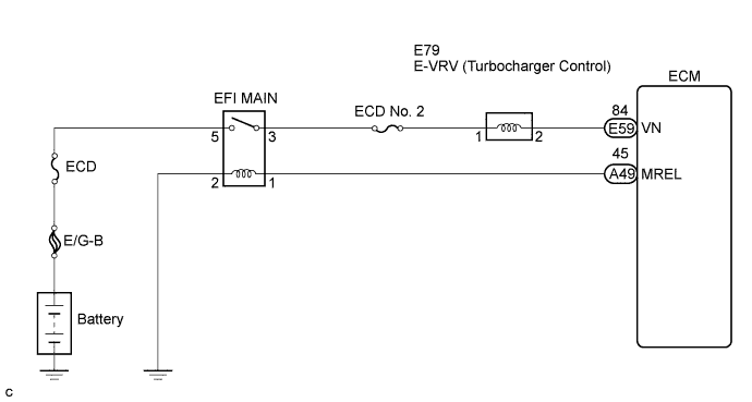
WIRING DIAGRAM
INSPECTION PROCEDURE
- NOTICE:
- After replacing the ECM, the new ECM needs registration (Click here) and initialization (Click here).
| 1.CHECK OTHER DTC OUTPUT (IN ADDITION TO DTC P0234, P0299 AND/OR P1251) |
Connect the intelligent tester to the DLC3.
Turn the engine switch ON (IG) and turn the intelligent tester ON.
Enter the following menus: "Powertrain / Engine / DTC".
Read DTCs.
- Result:
Display (DTC output)
| Proceed to
|
P0234, P0299 and/or P1251
| A
|
P0234, P0299 and/or P1251 and other DTCs
| B
|
| 2.CHECK CONNECTION OF VACUUM HOSES |
- HINT:
- Check the vacuum hoses of turbocharger system connections.
| | REPAIR OR REPLACE VACUUM HOSES |
|
|
| 3.CHECK VACUUM (TURBOCHARGER - E-VRV FOR TURBOCHARGER CONTROL) |
Using a three-way connector, connect a vacuum gauge to the hose between the E-VRV and turbocharger.
Warm up the engine coolant temperature to above 75°C (167°F).
Check the vacuum at the engine speed of 900 rpm.
- Result:
Vacuum
| Proceed to
|
0 kPa (0 mmHg, 0 in.Hg) to 50 kPa (375 mmHg, 14.8 in.Hg)
| A
|
Above 50 kPa (375 mmHg, 14.8 in.Hg)
| B
|
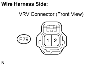
| 4.CHECK TERMINAL VOLTAGE (E-VRV POWER SOURCE) |
Disconnect the E79 E-VRV connector.
Measure the voltage.
- Standard voltage:
Tester Connection
| Specified Condition
|
VRV (E79-1) - Body ground
| 9 to 14 V
|
| | REPAIR OR REPLACE HARNESS OR CONNECTOR |
|
|
| 5.CHECK E-VRV FOR TURBOCHARGER CONTROL (E-VRV OPERATION) |
Check the E-VRV operation (Click here).
| | REPLACE E-VRV FOR TURBOCHARGER CONTROL |
|
|
| 6.CHECK E-VRV FOR TURBOCHARGER CONTROL (E-VRV RESISTANCE) |
Measure the E-VRV resistance (Click here).
- Standard resistance:
- 11.1 to 12.5 Ω
| | REPLACE E-VRV FOR TURBOCHARGER CONTROL |
|
|
| 7.CHECK HARNESS AND CONNECTOR (E-VRV FOR TURBOCHARGER CONTROL - ECM) |
Disconnect the E79 E-VRV connector.
Disconnect the E59 ECM connector.
Check the resistance between the wire harness side connectors.
- Standard resistance (Check for open):
Tester Connection
| Specified Condition
|
VN (E59-84) - VRV (E79-2)
| Below 1 Ω
|
- Standard resistance (Check for short):
Tester Connection
| Specified Condition
|
VN (E59-84) or VRV (E79-2) - Body ground
| 10 kΩ or higher
|
Reconnect the E-VRV connector.
Reconnect the ECM connector.
| | REPAIR OR REPLACE HARNESS OR CONNECTOR |
|
|
| 8.INSPECT TURBOCHARGER SUB-ASSEMBLY |
Check the turbocharging pressure (Click here).
- Standard:
- 48 to 53 kPa (0.49 to 0.54 kgf/cm2, 6.9 to 7.7 psi)
| | REPLACE TURBOCHARGER SUB-ASSEMBLY |
|
|
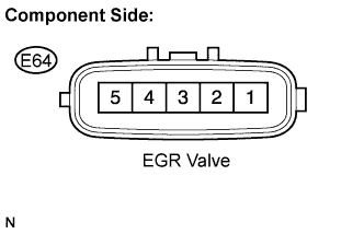
| 9.INSPECT EGR VALVE ASSEMBLY |
Disconnect the E64 EGR valve connector.
Measure the resistance between the terminals of the EGR valve.
- Standard resistance:
Tester Connection
| Condition
| Specified Condition
|
1 - 5
| 20°C (68°F)
| 6.5 to 7.5 Ω
|
Reconnect the EGR valve connector.
| | REPLACE EGR VALVE ASSEMBLY |
|
|
| 10.CHECK MANIFOLD ABSOLUTE PRESSURE SENSOR |
Connect an intelligent tester to the DLC3.
Turn the engine switch ON (IG) and turn the tester on.
Select the following menu items: Powertrain / Engine and ECT / Data List / Map and Atmosphere Pressure.
Read the value displayed on the tester.
- OK:
- MAP:
- Same as atmospheric pressure.
- HINT:
- 1 bar of atmospheric pressure is 101 kPa.
Apply a negative pressure of 40 kPa (300 mmHg, 11.8 in.Hg) to the manifold absolute pressure sensor.
- OK:
- MAP:
- MAP decreases 40 kPa from atmospheric pressure.
Apply a positive pressure of 69 kPa (518 mmHg, 20.4 in.Hg) to the manifold absolute pressure sensor.
- OK:
- MAP:
- MAP increases 69 kPa from atmospheric pressure.
- HINT:
- Even if the value output from the manifold absolute sensor is within the standard level, there may be a problem with the sensor due to deterioration because of age.
| | REPLACE MANIFOLD ABSOLUTE PRESSURE SENSOR |
|
|