Dtc P0100 Mass Or Volume Air Flow Circuit
Engine. Lexus Is250, Is220D. Gse20 Ale20
DESCRIPTION
WIRING DIAGRAM
INSPECTION PROCEDURE
READ VALUE OF INTELLIGENT TESTER (MAF)
INSPECT MASS AIR FLOW METER (POWER SOURCE CIRCUIT)
INSPECT MASS AIR FLOW METER (VG TERMINAL)
CHECK HARNESS AND CONNECTOR (MASS AIR FLOW METER - ECM)
CHECK HARNESS AND CONNECTOR (MASS AIR FLOW METER - EFI MAIN RELAY)
CHECK HARNESS AND CONNECTOR (SENSOR GROUND)
CHECK HARNESS AND CONNECTOR (MASS AIR FLOW METER - ECM)
DTC P0100 Mass or Volume Air Flow Circuit |
DTC P0102 Air Flow Meter Circuit Low Input |
DTC P0103 Air Flow Meter Circuit High Input |
DESCRIPTION
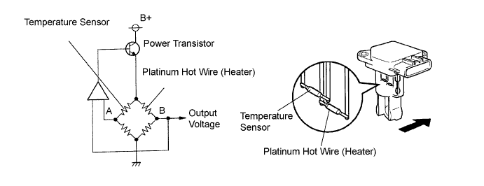
The mass air flow meter uses a platinum hot wire. The mass air flow meter consists of a platinum hot wire, a temperature sensor and a control circuit installed in a plastic housing. The mass air flow meter works on the principle that the hot wire and temperature sensor located in the intake air by-pass of the housing detect any changes in the intake air temperature.The hot wire is maintained at the predetermined temperature by controlling the current flow through the hot wire. This current flow is then related as the output voltage of the mass air flow meter.The circuit is constructed so that the platinum hot wire and temperature sensor provide a bridge circuit, with the power transistor controlled so that the potential of A and B remains equal to maintain the predetermined temperature.DTC No.
| DTC Detection Condition
| Trouble Area
|
P0100
| Open or short in mass air flow meter circuit for more than 3 seconds with engine speed at 4,000 rpm or less
(1 trip detection logic)
| - Open or short in mass air flow meter circuit
- Mass air flow meter
- ECM
|
P0102
| Open in mass air flow meter circuit for more than 3 seconds with engine speed at 4,000 rpm or less
(1 trip detection logic)
|
P0103
| Short in mass air flow meter circuit for more than 3 seconds with engine speed at 4,000 rpm or less
(1 trip detection logic)
|
- HINT:
- After confirming DTC P0100, P0102, or P0103, check the mass air flow ratio in the "Powertrain / Engine / Data List / MAF" using the intelligent tester.
Reference:Air Flow Value (gm/s)
| Malfunction
|
Approximately 0.0
| - Open in mass air flow meter power source circuit
- Open or short in VG circuit
|
174.0 or more
| Open in EVG circuit
|
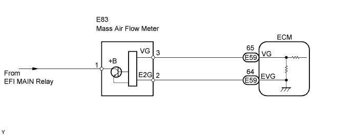
WIRING DIAGRAM
INSPECTION PROCEDURE
- NOTICE:
- After replacing the ECM, the new ECM needs registration (Click here) and initialization (Click here).
- HINT:
- If DTCs relating to different systems are output, and they share terminal E2 as their ground, check this ground circuit first.
| 1.READ VALUE OF INTELLIGENT TESTER (MAF) |
Connect the intelligent tester to the DLC3.
Start the engine.
Turn the intelligent tester ON.
Enter the following menus: "Powertrain / Engine / Data List / MAF" and read its value displayed on the intelligent tester.
- Result:
Air flow rate (gm/s)
| Proceed to
|
0.0
| A
|
174.0 or more
| B
|
Between 1 and 173.0 (*1)
| C
|
*1: The value should change when the throttle valve is opened or closed.
|
| |
|
| | CHECK FOR INTERMITTENT PROBLEMS |
|
|
| 2.INSPECT MASS AIR FLOW METER (POWER SOURCE CIRCUIT) |
Turn the engine switch ON (IG).
Disconnect the E83 mass air flow meter connector.
Measure the voltage between the terminal of the wire harness side connector and the body ground.
- Standard voltage:
Tester Connection
| Specified Condition
|
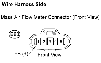
+B (E83-1) - Body ground
| 9 to 14 V
|
Reconnect the mass air flow meter connector.
| 3.INSPECT MASS AIR FLOW METER (VG TERMINAL) |
Output voltage inspection.
Disconnect the E83 MAF meter connector.
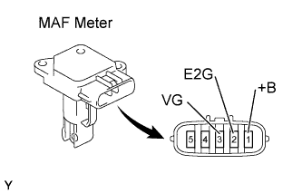
Apply battery voltage across terminals +B and E2G.
Connect the positive (+) tester probe to terminal VG, and negative (-) tester probe to terminal E2G.
Check the voltage.
- Standard voltage:
Tester Connection
| Specified Condition
|
VG (3) - E2G (2)
| 0.2 to 4.9 V
|
Reconnect the MAF meter connector.
| | REPLACE MASS AIR FLOW METER |
|
|
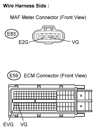
| 4.CHECK HARNESS AND CONNECTOR (MASS AIR FLOW METER - ECM) |
Disconnect the E83 MAF meter connector.
Disconnect the E59 ECM connector.
Measure the resistance.
- Standard resistance (Check for open):
Tester Connection
| Specified Condition
|
VG (E83-3) - VG (E59-65)
| Below 1 Ω
|
E2G (E83-2) - EVG (E59-64)
|
- Standard resistance (Check for short):
Tester Connection
| Specified Condition
|
VG (E83-3) or VG (E59-65) - Body ground
| 10 kΩ or higher
|
Reconnect the MAF meter connector.
Reconnect the ECM connector.
| | REPAIR OR REPLACE HARNESS OR CONNECTOR |
|
|
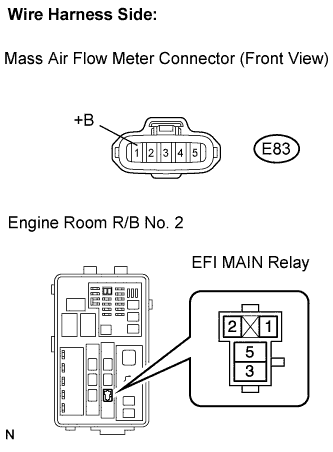
| 5.CHECK HARNESS AND CONNECTOR (MASS AIR FLOW METER - EFI MAIN RELAY) |
Disconnect the E83 MAF meter connector.
Remove the EFI MAIN relay from the engine room R/B No. 2.
Measure the resistance between the wire harness side connectors.
- Standard resistance (Check for open):
Tester Connection
| Specified Condition
|
+B (E83-1) - EFI MAIN relay (3)
| Below 1 Ω
|
- Standard resistance (Check for short):
Tester Connection
| Specified Condition
|
+B (E83-1) or EFI MAIN relay (3) - Body ground
| 10 kΩ or higher
|
Reconnect the MAF meter connector.
Reinstall the EFI MAIN relay.
| | REPAIR OR REPLACE HARNESS OR CONNECTOR |
|
|
| OK |
|
|
|
| CHECK ECM POWER SOURCE CIRCUIT |
|
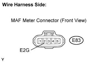
| 6.CHECK HARNESS AND CONNECTOR (SENSOR GROUND) |
Disconnect the E83 MAF meter connector.
Measure the resistance.
- Standard resistance:
Tester Connection
| Specified Condition
|
E2G (E83-2) - Body ground
| Below 1 Ω
|
Reconnect the MAF meter connector.
| | REPLACE MASS AIR FLOW METER |
|
|
| 7.CHECK HARNESS AND CONNECTOR (MASS AIR FLOW METER - ECM) |
Disconnect the E83 MAF meter connector.
Disconnect the E59 ECM connector.
Measure the resistance.
- Standard resistance (Check for open):
Tester Connection
| Specified Condition
|
VG (E83-3) - VG (E59-65)
| Below 1 Ω
|
E2G (E83-2) - EVG (E59-64)
|
- Standard resistance (Check for short):
Tester Connection
| Specified Condition
|
VG (E83-3) or VG (E59-65) - Body ground
| 10 kΩ or higher
|
Reconnect the MAF meter connector.
Reconnect the ECM connector.
| | REPAIR OR REPLACE HARNESS OR CONNECTOR |
|
|