Fuel Supply Pump Installation
Engine. Lexus Is250, Is220D. Gse20 Ale20
INSTALL SUPPLY PUMP ASSEMBLY
INSTALL FUEL INLET PIPE SUB-ASSEMBLY
INSTALL FUEL TUBE SUB-ASSEMBLY
INSTALL NO. 3 FUEL HOSE
INSTALL NO. 1 INTAKE MANIFOLD INSULATOR
INSTALL WIRING HARNESS CLAMP BRACKET
INSTALL NO. 5 FUEL HOSE
INSTALL NO. 1 FUEL PIPE
INSTALL ENGINE ASSEMBLY
Fuel Supply Pump -- Installation |
| 1. INSTALL SUPPLY PUMP ASSEMBLY |
Install a new O-ring to the supply pump assembly.
Install the supply pump drive coupling.
- HINT:
- Line up the coupling with the groove in the camshaft end.
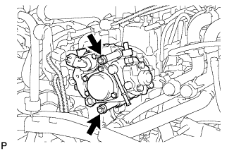
Install the supply pump assembly with the 2 bolts.
- Torque:
- 21 N*m{210 kgf*cm, 15 ft.*lbf}
- NOTICE:
- Apply engine oil to the O-ring on the supply pump assembly.
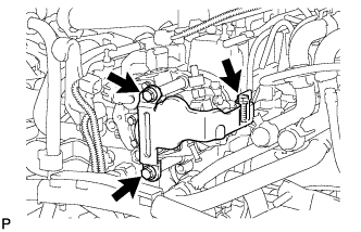
Install the No. 1 injection pump protector with the 3 bolts.
- Torque:
- 20 N*m{204 kgf*cm, 15 ft.*lbf}
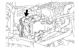
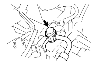
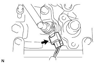
Connect the suction control valve connector.
| 2. INSTALL FUEL INLET PIPE SUB-ASSEMBLY |
- NOTICE:
- In cases where the supply pump is replaced, the fuel inlet pipe must also be replaced.
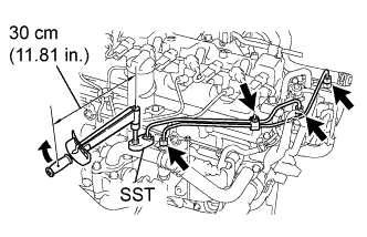
Temporarily install the fuel inlet pipe with the 2 clamps and nut.
Using the SST, first tighten the nut at the common rail end of the fuel inlet pipe.
- SST
- 09023-38401
- Torque:
- 27 N*m{275 kgf*cm, 20 ft.*lbf}
- HINT:
- Use of the proper SST is necessary to ensure that the correct torque is applied to the injection pipe nut.
- Use a torque wrench with a fulcrum length of 30 cm (11.81 in.).
- Make sure that the pipe is not deformed or twisted during installation.
- If the pipe is deformed or twisted, or if it cannot be installed properly, replace the pipe with a new one.
Using the SST, tighten the nut at the supply pump end of the fuel inlet pipe.
- SST
- 09023-38401
- Torque:
- 27 N*m{275 kgf*cm, 20 ft.*lbf}
- HINT:
- Use of the proper SST is necessary to ensure that the correct torque is applied to the injection pipe nut.
- Use a torque wrench with a fulcrum length of 30 cm (11.81 in.).
- Make sure that the pipe is not deformed or twisted during installation.
- If the pipe is deformed or twisted, or if it cannot be installed properly, replace the pipe with a new one.
Tighten the fuel inlet pipe clamp nut.
- Torque:
- 5.0 N*m{51 kgf*cm, 44 in.*lbf}
| 3. INSTALL FUEL TUBE SUB-ASSEMBLY |
Install the fuel tube and gasket with the union bolt.
- Torque:
- 23 N*m{235 kgf*cm, 17 ft.*lbf}
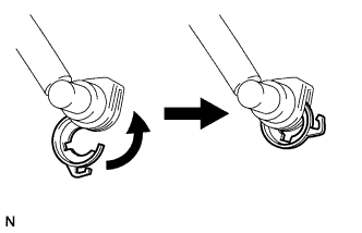
Turn the retainer in the direction indicated by the arrow until it stops.
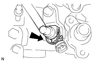
Insert the fuel tube connector into the injector.
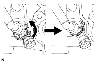
Turn the retainer in the direction indicated by the arrow until it makes a "click" sound.
- NOTICE:
- If the fuel tube connector is not inserted into the correct position on the injector, the retainer will not turn beyond the point indicated in the illustration.
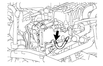
Connect the exhaust fuel addition injector connector.
| 4. INSTALL NO. 3 FUEL HOSE |
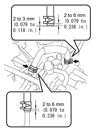
Using pliers, slide the 2 clips to install the No. 3 fuel hose as shown in the illustration.
| 5. INSTALL NO. 1 INTAKE MANIFOLD INSULATOR |
- HINT:
- Click here
| 6. INSTALL WIRING HARNESS CLAMP BRACKET |
- HINT:
- Click here
| 7. INSTALL NO. 5 FUEL HOSE |
Using pliers, slide the clip to install the No. 5 fuel hose.
| 8. INSTALL NO. 1 FUEL PIPE |
- HINT:
- Click here
| 9. INSTALL ENGINE ASSEMBLY |
- HINT:
- Click here