Power Door Lock Control System Door Opening Relay Power Source Circuit
DESCRIPTION
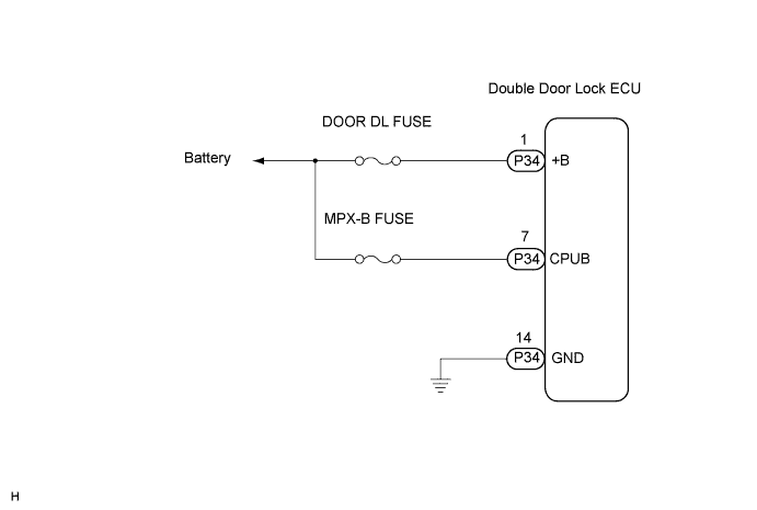
WIRING DIAGRAM
INSPECTION PROCEDURE
CHECK WIRE HARNESS (DOUBLE DOOR LOCK ECU - BATTERY AND BODY GROUND)
POWER DOOR LOCK CONTROL SYSTEM - Door Opening Relay Power Source Circuit |
DESCRIPTION
This circuit supplies power to operate the double door lock ECU (door opening relay).
WIRING DIAGRAM
INSPECTION PROCEDURE
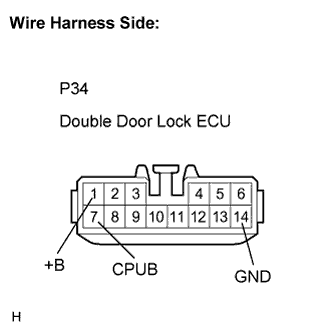
| 1.CHECK WIRE HARNESS (DOUBLE DOOR LOCK ECU - BATTERY AND BODY GROUND) |
Disconnect the double door lock ECU (door opening relay) connector.
Measure the resistance according to the value(s) in the table below.
- Standard resistance:
Tester Connection
(Symbols)
| Condition
| Specified Condition
|
P34-14 (GND) - Body ground
| Always
| Below 1 Ω
|
Measure the voltage according to the value(s) in the table below.
- Standard voltage:
Tester Connection
(Symbols)
| Condition
| Specified Condition
|
P34-1 (+B) - Body ground
| Always
| 10 to 14 V
|
P34-7 (CPUB) - Body ground
| Always
| 10 to 14 V
|
| | REPAIR OR REPLACE HARNESS OR CONNECTOR |
|
|
| OK |
|
|
|
| PROCEED TO NEXT CIRCUIT INSPECTION SHOWN IN PROBLEM SYMPTOMS TABLE |
|