Dtc B2762 Intrusion Sensor Signal Circuit Malfunction
DESCRIPTION
WIRING DIAGRAM
INSPECTION PROCEDURE
CHECK HARNESS AND CONNECTOR (MAIN BODY ECU RH - PERSONAL LIGHT ASSEMBLY)
CHECK OPERATION OF INTRUSION SENSOR
DTC B2762 Intrusion Sensor Signal Circuit Malfunction |
DESCRIPTION
- The intrusion sensor conducts self-diagnosis immediately after power is supplied to the sensor (when the theft deterrent system is set).
If a malfunction is detected in the IOUT - ISIF line, the main body ECU RH outputs this DTC.
DTC No.
| DTC Detection Condition
| Trouble Area
|
B2762
| After normal/trouble signal is output from intrusion sensor as result of self-diagnosis, following malfunctions are detected:
- IOUT - ISIF line circuit is open
- Reception of signals other than normal/trouble signal
| - Intrusion sensor
- Wire harness
- Main body ECU RH (Cowl side J/B RH)
|
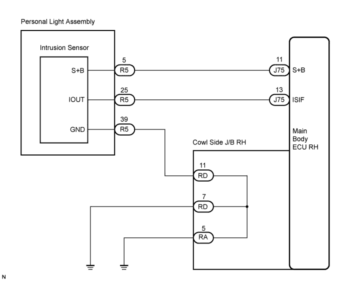
WIRING DIAGRAM
INSPECTION PROCEDURE
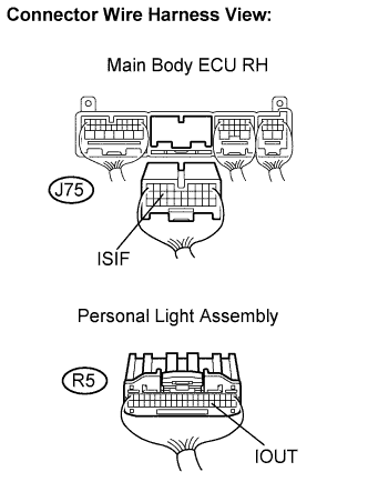
| 1.CHECK HARNESS AND CONNECTOR (MAIN BODY ECU RH - PERSONAL LIGHT ASSEMBLY) |
Disconnect the J75 ECU connector and R5 light connector.
Measure the resistance according to the value(s) in the table below.
- Standard resistance:
Symbol (Tester Connection)
| Specified Condition
|
ISIF (J75-13) - IOUT (R5-25)
| Below 1 Ω
|
ISIF (J75-13) - Body ground
| 10 kΩ or higher
|
| | REPAIR OR REPLACE HARNESS OR CONNECTOR |
|
|
| 2.CHECK OPERATION OF INTRUSION SENSOR |
Temporarily replace the personal light assembly with a new or normally functioning sensor.
Check if the DTC B2762 is not output.
- OK:
- DTC B2762 is not output.
| | REPLACE MAIN BODY ECU RH (COWL SIDE JUNCTION BLOCK RH) |
|
|
| OK |
|
|
|
| REPLACE PERSONAL LIGHT ASSEMBLY (INTRUSION SENSOR) |
|