Meter / Gauge System Speedometer Malfunction
Meter. Lexus Is250, Is220D. Gse20 Ale20
DESCRIPTION
WIRING DIAGRAM
INSPECTION PROCEDURE
PERFORM ACTIVE TEST BY INTELLIGENT TESTER
READ VALUE OF INTELLIGENT TESTER
READ VALUE OF INTELLIGENT TESTER
INSPECT COMBINATION METER ASSEMBLY
INSPECT COMBINATION METER ASSEMBLY
CHECK HARNESS AND CONNECTOR (COMBINATION METER - ABS & TRACTION ACTUATOR ASSEMBLY)
CHECK HARNESS AND CONNECTOR (COMBINATION METER - SKID CONTROL ECU)
METER / GAUGE SYSTEM - Speedometer Malfunction |
DESCRIPTION
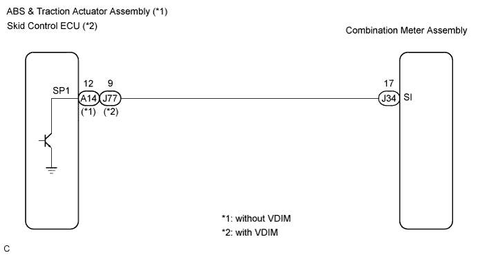
- The meter CPU receives vehicle speed signals from this circuit.
- The vehicle speed sensor detects the voltage that varies according to the vehicle speed.
- The ABS & traction actuator assembly supplies power to the vehicle speed sensor.
- The ABS & traction actuator assembly detects vehicle speed signals based on the pulses of the voltage.
- The ABS & traction actuator assembly transmits vehicle speed signals as pulses to the meter CPU.
- The meter CPU calculates the vehicle speed converting 4 pulses to 1 revolution.
- HINT:
- If the vehicle has a VDIM function, the skid control ECU is built into the ABS & traction actuator assembly.
WIRING DIAGRAM
INSPECTION PROCEDURE
- HINT:
- Before starting circuit inspection, check tire size and tire pressure.
| 1.PERFORM ACTIVE TEST BY INTELLIGENT TESTER |
Connect the tester to the DLC3.
Turn the engine switch on (IG).
Turn the tester ON.
Enter the following menus: Diagnosis / Body / Combination Meter / Active Test.
Check the values by referring to the table below.
Combination Meter:Item
| Test Details
| Diagnostic Note
|
Speed Meter Operation
| 0, 40, (24), 80 (48), 120 (72), 160 (96), 200 (120) km/h (mph)
| -
|
- OK:
- Needle indication is within the allowable range.
| | REPLACE COMBINATION METER ASSEMBLY |
|
|
| 2.READ VALUE OF INTELLIGENT TESTER |
Connect the intelligent tester to the DLC3.
Turn the engine switch on (IG).
Turn the tester ON.
Enter the following menus: Diagnosis / Body / Combination Meter / Data List.
Check the values by referring to the table below.
Combination Meter:Item
| Measurement Item/Range (Display)
| Normal Condition
| Diagnostic Note
|
Vehicle Speed Meter
| Vehicle speed/Min.: 0 km/h (0 mph), Max.: 255 km/h (158 mph)
| Almost same as actual speed (When driving)
| -
|
- OK:
- Vehicle speed displayed on the tester is almost the same as the actual vehicle speed measured using a speedometer tester (calibrated chassis dynamometer).
| OK |
|
|
|
| REPLACE COMBINATION METER ASSEMBLY |
|
| 3.READ VALUE OF INTELLIGENT TESTER |
Connect the intelligent tester to the DLC3.
Turn the engine switch on (IG).
Turn the tester ON.
Enter the following menus: Diagnosis / Power Train / ABS/VSC/TRAC / Data List.
Check the values by referring to the table below.
ABS/VSC/TRAC:Item
| Measurement Item/Range (Display)
| Normal Condition
| Diagnostic Note
|
(FL/FR/RL/RR) Wheel Spd
| Vehicle speed/Min.: 0 km/h (0 mph), Max.: 326 km/h (202 mph)
| Almost same as actual speed (When driving)
| -
|
- OK:
- Vehicle speed displayed on the tester is almost the same as the actual vehicle speed.
| | GO TO BRAKE CONTROL SYSTEM |
|
|
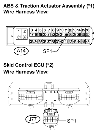
| 4.INSPECT COMBINATION METER ASSEMBLY |
Disconnect the A14 (*1) / J77 (*2) connector.
Measure the voltage according to the value(s) in the table below.
- Standard voltage:
Tester Connection
| Condition
| Specified Condition
|
A14-12 (SP1) (*1) - Body ground
| Engine switch on (IG)
| 10 to 14 V
|
J77-9 (SP1) (*2) - Body ground
| Engine switch on (IG)
| 10 to 14 V
|
*1: without VDIM*2: with VDIM- Result:
Result
| Proceed to
|
OK
| A
|
NG (without VDIM)
| B
|
NG (with VDIM)
| C
|
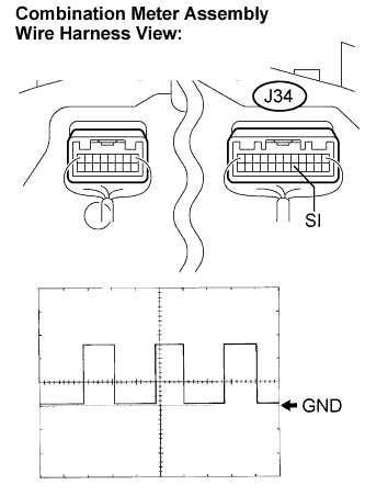
| 5.INSPECT COMBINATION METER ASSEMBLY |
Check the input signal waveform.
Remove the combination meter assembly with the connector(s) still connected.
Connect the oscilloscope to terminals J34-17 (SI) and body ground.
Turn the engine switch on (IG).
Turn the wheel slowly.
Check the signal waveform according to the condition(s) in the table below.
Item
| Condition
|
Tool setting
| 5 V/DIV., 20 ms./DIV.
|
Vehicle condition
| Driving at approx. 20 km/h (12 mph)
|
- OK:
- The waveform is displayed as shown in the illustration.
- HINT:
- As the vehicle speed increases, the cycle of the signal waveform narrows.
ResultResult
| Proceed to
|
OK
| A
|
NG (without VDIM)
| B
|
NG (with VDIM)
| C
|
| | REPLACE ABS & TRACTION ACTUATOR ASSEMBLY |
|
|
| |
|
| A |
|
|
|
| REPLACE COMBINATION METER ASSEMBLY |
|
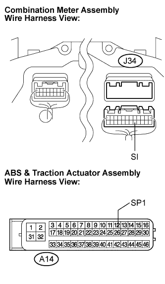
| 6.CHECK HARNESS AND CONNECTOR (COMBINATION METER - ABS & TRACTION ACTUATOR ASSEMBLY) |
Disconnect the J34 and A14 connectors.
Measure the resistance according to the value(s) in the table below.
- Standard resistance:
Tester Connection
| Condition
| Specified Condition
|
A14-12 (SP1) - J34-17 (SI)
| Always
| Below 1 Ω
|
A14-12 (SP1) - Body ground
| Always
| 10 kΩ or higher
|
| | REPAIR OR REPLACE HARNESS OR CONNECTOR |
|
|
| OK |
|
|
|
| REPLACE COMBINATION METER ASSEMBLY |
|
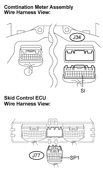
| 7.CHECK HARNESS AND CONNECTOR (COMBINATION METER - SKID CONTROL ECU) |
Disconnect the J34 and J77 connectors.
Measure the resistance according to the value(s) in the table below.
- Standard resistance:
Tester Connection
| Condition
| Specified Condition
|
J77-9 (SP1) - J34-17 (SI)
| Always
| Below 1 Ω
|
J77-9 (SP1) - Body ground
| Always
| 10 kΩ or higher
|
| | REPAIR OR REPLACE HARNESS OR CONNECTOR |
|
|
| OK |
|
|
|
| REPLACE COMBINATION METER ASSEMBLY |
|