Meter / Gauge System -- System Description |
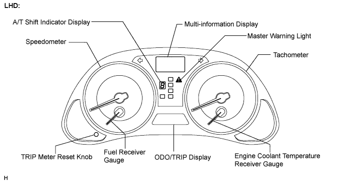
| METER GAUGE |
*2: with Navigation System
*3: with Intelligent AFS
*4: with Pre-crash Safety System
*5: for 2AD-FHV
*6: with Dynamic Radar Cruise Control System
*7: for Automatic Transmission
| Item | Detail |
| Speedometer | Indicates the vehicle speed based on a signal received from the ABS & traction actuator assembly. (Direct Line) |
| Tachometer | Indicates the engine speed based on a signal received from the ECM. (Direct Line) |
| Fuel Gauge | Receives a fuel signal from the two fuel sender gauges (main and sub). (Direct Line) |
| Engine Coolant Temperature Receiver Gauge | Indicates the engine coolant temperature based on a signal received from the ECM. (CAN-BEAN) |
| Item | Detail |
| TURN SIGNAL | Receives a turn signal from the turn signal flasher. (Direct Line) |
| BEAM | Receives a beam signal from the main body ECU RH (Cowl Side J/B RH). (BEAN) |
| CHECK E/G | Receives a check engine signal from the ECM. (Direct Line) |
| DOOR | Receives a door condition signal from the main body ECU RH (Cowl Side J/B RH). (BEAN) |
| D-BELT | Receives a driver side seat belt signal from the center airbag sensor assembly. (CAN-BEAN) |
| P-BELT | Receives a front passenger side seat belt signal from the center airbag sensor assembly and transmits a front passenger side seat belt condition signal to the integration control & panel assembly (*1)/multi-display (*2). (Direct Line) |
| TAIL | Receives a taillight signal from the main body ECU RH (Cowl Side J/B RH). (BEAN) |
| A/T SHIFT | Receives an A/T shift condition signal from the park/neutral position switch and the ECM. (CAN-BEAN) |
| FUEL | Receives a fuel signal from the fuel sender gauges (main and sub). (Direct Line) |
| ABS | Receives an ABS signal from the ABS & traction actuator assembly. (CAN-BEAN) |
| SLIP | Receives a SLIP signal from the ABS & traction actuator assembly. (CAN-BEAN) |
| BRAKE | Receives a BRAKE signal from the ABS & traction actuator assembly. (CAN-BEAN) |
| CRUISE | Receives a cruise signal from the ECM. (CAN-BEAN) |
| AIRBAG | Receives an airbag signal from the center airbag sensor assembly. (CAN-BEAN) |
| AFS OFF (*3) | Receives an AFS OFF signal from the AFS ECU. (BEAN) |
| EPS | Receives an EPS signal from the EPS ECU. (CAN-BEAN) |
| PCS (*4) | Receives a PCS signal from the seat belt control ECU. (CAN-BEAN) |
| Speed warning | Receive a vehicle speed signal from the ABS & traction actuator assembly and displays a speed indicator setting set with the satellite switch. (Direct Line) |
| Tach warning | Receive a tachometer signal from the ECM and displays a tach indicator setting set with the satellite switch. (Direct Line) |
| Sediment (*5) | Receives a sediment signal from the fuel sediment switch. (Direct Line) |
| Glow (*5) | Receives a glow signal from the ECM. (CAN-BEAN) |
| Oil maintenance (*5) | Receives the date when the oil maintenance is completed from the ECM. (CAN-BEAN) |
- HINT:
- The multi-information display is located in the center of the combination meter assembly.
- The display shows a message or animation for each of the functions described in the table below.
| Item | Detail |
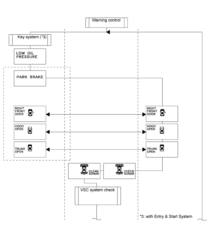
| Door warning | When a door (front passenger, back and hood) of the vehicle is opened or closed, the dot comes on to inform the driver of the condition of the door. |
| Outside temperature display | Displays an outside temperature in accordance with an ambient temperature signal from the A/C control amplifier. |
| Instant fuel consumption |
|
| Average fuel consumption |
|
| Dynamic radar cruise control system display (*6) | Displays a description of the operation while the dynamic radar cruise control system is operating. |
| A/T gear position signal | Displays the A/T gear position and A/T range receiving a signal from the ECM. (*7) |
| Warning message | Illuminates or blinks the master warning light and displays a warning message for each type of system failure. |
| DTC (Diagnostic Trouble Code) display | Displays the 2 digit DTCs pertaining to the VSC function. |
| Item | Display |
| ODO/TRIP display | This display switches between odometer, trip meter A, and trip meter B in accordance with the operation of the ODO/TRIP switch. |
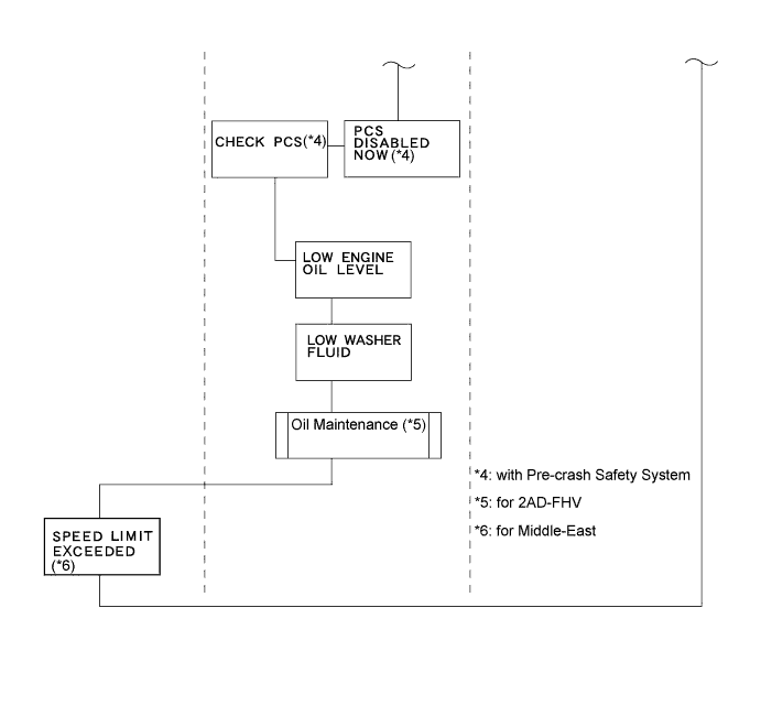
| Maintenance required (*5) | An oil maintenance required indication will display to remind the driver to change the engine oil depending on the vehicle driving distance. |
| ILLUMINATION CONTROL |
- HINT:
- If the engine switch is turned on (IG), the illumination control operates as follows. However, all illuminations other than the tachometer needle turn off while cranking the engine.
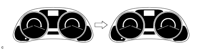
The speedometer and tachometer needles illuminate starting from the base of the needles and moving to their tips.
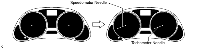
These needles move to their maximum position and return to zero.
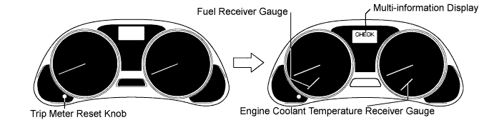
The fuel gauge and water temperature gauge light up, then the warning lights, indicator lights, multi-information display, and meter panel illumination come on.
| MULTI-INFORMATION DISPLAY |
*2: with Clearance Sonar System
*3: with Intrusion Sensor
*4: with Intelligent AFS
*5: for 2AD-FHV
*6: with Dynamic Radar Cruise Control System
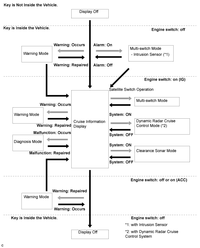
| Mode | Outline |
| Cruise Information |
|
| Warning | The warning mode display will interrupt the multi-information display immediately when a warning occurs. |
| Multi-switch |
|
| Dynamic Radar Cruise Display (*6) | Displays the operating condition of the dynamic radar cruise control. |
| Parking Assist-sensor Display | Displays the location of an obstacle and the approximate distance between the vehicle and the obstacle and displays malfunction warning messages about sensor freezing or presence of dirt on the sensors. |
| Diagnosis | DTCs (Diagnostic Trouble Codes) for the brake control system can be displayed. |
| INTEGRATION CONTROL & PANEL ASSEMBLY (without NAVIGATION SYSTEM)/MULTI-DISPLAY (with NAVIGATION SYSTEM) |
*2: with Navigation System
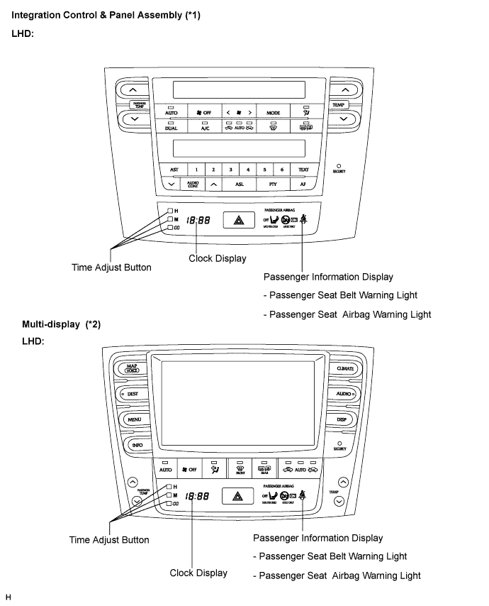
- HINT:
- The integration control & panel assembly (*1) consists of two parts (passenger information display and heater control panel). These areas display the contents given in the table below.
- The multi-display (*2) consists of four parts (navigation display, passenger information display, clock display, and heater control panel). These areas display the contents given in the table below.
| Item | Detail |
| Passenger information display | Displays the condition of the front passenger seat belt ON/OFF and the front passenger seat airbag ON/OFF. |
| Heater control panel | Displays the condition of the heater control panel. |
| Clock display (in the clock assembly) | Displays the time. |
| Navigation display (*2) | Displays the navigation data. |
| MULTI-INFORMATION DISPLAY FLOW-CHART |
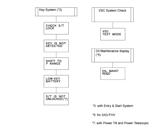
| DIAGNOSIS SYSTEM |

The combination meter assembly indicates the diagnosis mode by blinking the warning light or by blinking the warning message in the multi-information display.
- HINT:
- The multi-information display shows "DIAG" when the engine switch is on (IG) (Click here).
- Diagnosis information can be displayed on the multi-information display after connecting a jumper wire between terminals TC (J21-13) and CG (J21-4) of the DLC3 connector.
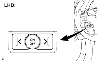
| SATELLITE SWITCH |
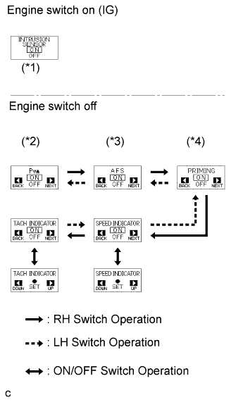
By using the satellite switch (RH switch, ON/OFF switch, LH switch), 6 different switch functions can be displayed and changed (SPEED indicator, TACH indicator, Intrusion sensor (*1), Clearance sonar (*2), AFS (*3), Priming (*4)).
- While driving at 3 mph (5 km/h) or less, the switch except for clearance sonar (SPEED indicator, TACH indicator, Intrusion sensor (*1), AFS (*3), Priming (*4)) can be displayed.
- The switch functions displayed are changed in the order shown in the illustration using the satellite switch (RH switch, LH switch). The function can be set using the ON/OFF switch.
- The display automatically returns to the previous display 6 seconds after the satellite switch is operated. It will return to the previous display immediately if the DISP switch is operated.
*2: with Clearance Sonar System
*3: with Intelligent AFS
*4: for 2AD-FHV- While driving at 3 mph (5 km/h) or less, the switch except for clearance sonar (SPEED indicator, TACH indicator, Intrusion sensor (*1), AFS (*3), Priming (*4)) can be displayed.
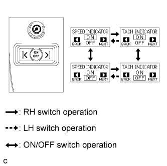
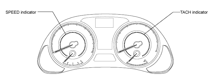
SPEED and TACH indicator
- The SPEED indicator and TACH indicator come on when the vehicle speed or engine speed reaches the speed set using the satellite switch. The setting ranges of these indicators are shown in the table that follows.
- Vehicle speed or engine speed can be set using the satellite switch.
- These indicators consist of yellow and red dots that are arranged to form indicator rings.
- When the set vehicle speed or engine speed is reached while driving, the red and yellow dots will turn on at the same time to cause amber light to illuminate the indicator ring.
- However, if the vehicle or engine speed is set to the maximum speed of the indicator setting range, and the speed reaches this set speed, only red light will illuminate the indicator ring.
- HINT:
Speed Indicator: Destination Setting Range Initial Setting LHD 50 to 200 (km/h) 130 (km/h) RHD Cypriot and Irish 50 to 160 (km/h) 120 (km/h) Others 30 to 100 (mph) 75 (mph) Tach Indicator: Engine Setting Range Initial Setting 4GR-FSE 2,000 to 6,500 (rpm) 5,000 (rpm) 2AD-FHV 2,000 to 5,100 (rpm) 4,000 (rpm) - The SPEED indicator and TACH indicator come on when the vehicle speed or engine speed reaches the speed set using the satellite switch. The setting ranges of these indicators are shown in the table that follows.
  |
  |