Navigation System Navigation Ecu Power Source Circuit
DESCRIPTION
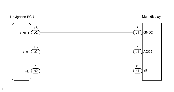
WIRING DIAGRAM
INSPECTION PROCEDURE
INSPECT MULTI-DISPLAY
CHECK HARNESS AND CONNECTOR (NAVIGATION ECU - MULTI-DISPLAY)
NAVIGATION SYSTEM - Navigation ECU Power Source Circuit |
DESCRIPTION
This is the power source circuit to operate the navigation ECU.
WIRING DIAGRAM
INSPECTION PROCEDURE
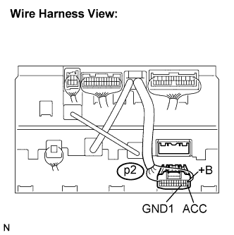
Disconnect the navigation ECU connector p2.
Measure the resistance according to the value(s) in the table below.
- Standard resistance:
Tester connection
| Condition
| Specified condition
|
GND1 - Body ground
| Always
| Below 1 Ω
|
Measure the voltage according to the value(s) in the table below.
- Standard voltage:
Tester connection
| Condition
| Specified condition
|
+B - GND1
| Always
| 10 to 14 V
|
ACC - GND1
| Engine switch on (ACC)
| 10 to 14 V
|
| OK |
|
|
|
| PROCEED TO NEXT CIRCUIT INSPECTION SHOWN IN PROBLEM SYMPTOMS TABLE |
|
| 2.CHECK HARNESS AND CONNECTOR (NAVIGATION ECU - MULTI-DISPLAY) |
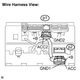
Disconnect the navigation ECU connector p2 and multi-display connector p1.
Measure the resistance according to the value(s) in the table below.
- Standard resistance:
Tester connection
| Condition
| Specified condition
|
GND1 - GND2
| Always
| Below 1 Ω
|
ACC - ACC2
| Always
| Below 1 Ω
|
+B - +B
| Always
| Below 1 Ω
|
GND1 - Body ground
| Always
| 10 kΩ or higher
|
ACC - Body ground
| Always
| 10 kΩ or higher
|
+B - Body ground
| Always
| 10 kΩ or higher
|
| | REPAIR OR REPLACE HARNESS OR CONNECTOR |
|
|