Theft Deterrent System (W/O Intrusion Sensor) Ecu Power Source Circuit
DESCRIPTION
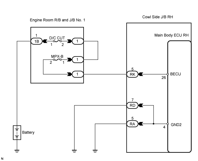
WIRING DIAGRAM
INSPECTION PROCEDURE
INSPECT FUSE (D/C CUT, MPX-B)
CHECK COWL SIDE JUNCTION BLOCK RH (POWER SOURCE)
CHECK HARNESS AND CONNECTOR (COWL SIDE J/B RH - BODY GROUND)
THEFT DETERRENT SYSTEM (w/o Intrusion Sensor) - ECU Power Source Circuit |
DESCRIPTION
This circuit provides power for main body ECU RH operation.
WIRING DIAGRAM
INSPECTION PROCEDURE
| 1.INSPECT FUSE (D/C CUT, MPX-B) |
Remove the D/C CUT and MPX-B fuses from the engine room R/B and J/B No. 1.
Measure the resistance.
- Standard resistance:
- Below 1 Ω
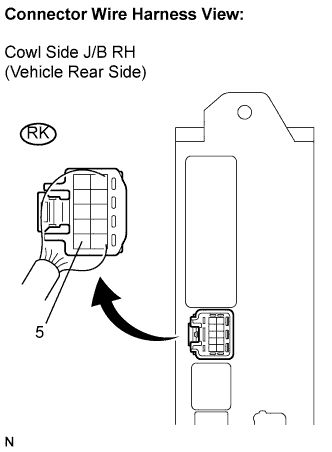
| 2.CHECK COWL SIDE JUNCTION BLOCK RH (POWER SOURCE) |
Install the D/C CUT and MPX-B fuses to the engine room R/B and J/B No. 1.
Disconnect the RK J/B connector.
Measure the voltage according to the value(s) in the table below.
- Standard voltage:
Symbol (Tester Connection)
| Specified Condition
|
RK-5 - Body ground
| 10 to 14 V
|
| | REPAIR OR REPLACE HARNESS OR CONNECTOR |
|
|
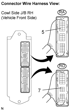
| 3.CHECK HARNESS AND CONNECTOR (COWL SIDE J/B RH - BODY GROUND) |
Disconnect the RD and RA J/B connectors.
Measure the resistance according to the value(s) in the table below.
- Standard resistance:
Symbol (Tester Connection)
| Specified Condition
|
RD-7 - Body ground
| Below 1 Ω
|
RA-5 - Body ground
|
| | REPAIR OR REPLACE HARNESS OR CONNECTOR |
|
|
| OK |
|
|
|
| PROCEED TO NEXT CIRCUIT INSPECTION SHOWN IN PROBLEM SYMPTOMS TABLE |
|