Engine. Lexus Is250, Is220D. Gse20 Ale20
DESCRIPTION
WIRING DIAGRAM
INSPECTION PROCEDURE
CHECK IF ENGINE START (INITIALIZE STEERING LOCK)
CHECK FOR DTC
CHECK SWITCH CONDITION
CHECK CRANKING FUNCTION
READ VALUE OF INTELLIGENT TESTER (STA SIGNAL)
READ VALUE OF INTELLIGENT TESTER (STOP LIGHT SWITCH)
READ VALUE OF INTELLIGENT TESTER (STEERING LOCK)
CHECK STEERING LOCK
INSPECT ECM (STAR AND STSW VOLTAGE)
INSPECT RELAY (ST CUT)
INSPECT PARK/NEUTRAL POSITION SWITCH (A/T) OR CLUTCH START SWITCH (M/T)
INSPECT RELAY (STARTER)
CHECK HARNESS AND CONNECTOR (PNP SWITCH (A/T) OR CLUTCH START SWITCH (M/T) - ST RELAY)
INSPECT ENGINE ROOM RELAY BLOCK (STARTER RELAY VOLTAGE)
INSPECT STARTER ASSEMBLY
CHECK HARNESS AND CONNECTOR (POWER SOURCE CONTROL ECU - ECM)
CHECK AND REPLACE POWER SOURCE CONTROL ECU
READ VALUE OF INTELLIGENT TESTER (L CODE)
READ VALUE OF INTELLIGENT TESTER (ENGINE START REQUEST)
READ VALUE OF INTELLIGENT TESTER (S CODE)
INSPECT ID CODE BOX
CHECK WIRE HARNESS (POWER SOURCE CONTROL ECU - STEERING LOCK ECU)
INSPECT POWER SOURCE CONTROL ECU
INSPECT STEERING LOCK ECU
ENTRY AND START SYSTEM - Engine does not Start |
DESCRIPTION
| ENGINE START SYSTEM OPERATION |
A/T Models: If the engine switch is pressed with the shift lever in P or N and the brake pedal depressed, the power source control ECU determines that it is an engine start request.
M/T Models: If the engine switch is pressed with the clutch pedal depressed, the power source control ECU determines that it is an engine start request.
The certification ECU and other ECUs perform key verification via the LIN communication line.
The power source control ECU activates the ACC relay.
The power source control ECU activates the IG1 and IG2 relays.
The certification ECU outputs a steering UNLOCK signal. The signal is sent to the power source control ECU via the steering lock ECU.
The power source control ECU sends an engine start request signal to the ECM.
The ECM sends an ACC cut request signal to the power source control ECU.
The ECM and power source control ECU activate the ST relay.
The power source control ECU deactivates the ACC relay until the ECU detects an engine start.
When engine revolution speed reaches 200 rpm, the power source control ECU determines that the engine has been started.
The ECU reactivates the ACC relay and turns off the engine switch indicator light.
Symbols of power source control ECU
| Signals
|
STP
| Stop light switch ON signal
|
SSW1/SSW2
| Engine switch ON signal
|
ACCD
| ACC relay operation signal
|
IG2D
| IG2 relay operation signal
|
STR2
| ST relay operation signal
|
STR1
| Park/neutral position switch signal (A/T), Clutch start switch (M/T)
|
TACH
| Engine start detection signal
|
STSW
| Starter activation request signal
|
CTSW
| ACC cut request signal
|
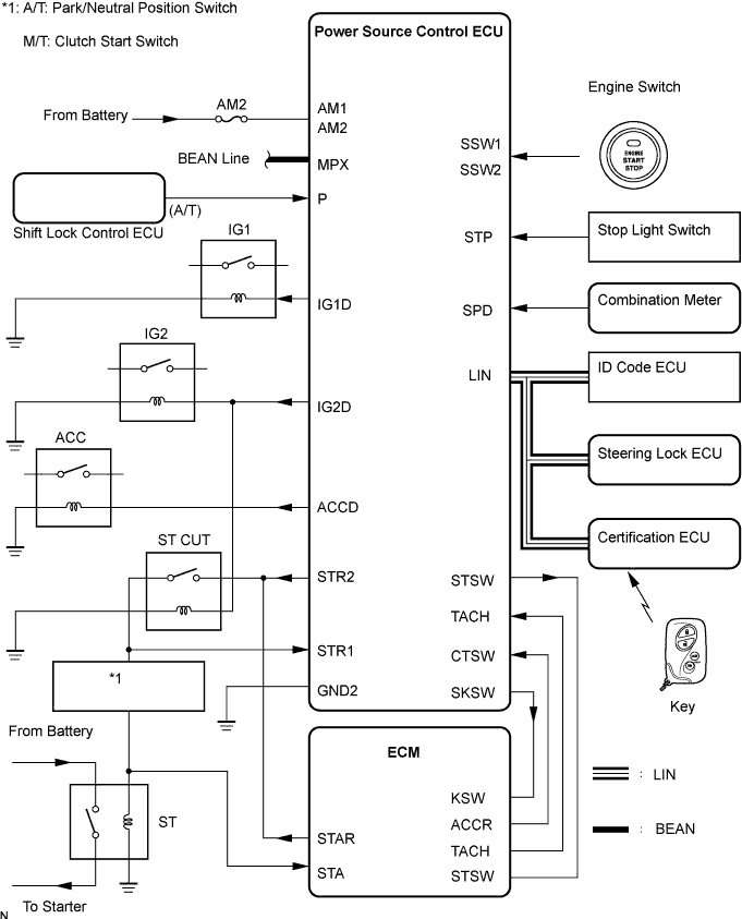
WIRING DIAGRAM
See CRANKING HOLDING FUNCTION CIRCUIT (Click here).
INSPECTION PROCEDURE
| 1.CHECK IF ENGINE START (INITIALIZE STEERING LOCK) |
Shift lever is in the P position.
Open and close the driver's door with the engine switch off. Check if the engine can be started.
- OK:
- Engine can be started.
- HINT:
- After the battery is discharged and then recharged, the engine may not start unless the steering lock is initialized using the above procedure.
Delete the DTCs (Click here).
Check for DTCs again.
- OK:
- No DTC is output.
Check the engine start function.
A/T Models: When the key is inside the vehicle and the shift lever is in P, check that pressing the engine switch causes the power source mode to change as follows.
M/T Models: When the key is inside the vehicle, check that pressing the engine switch causes the power source mode to change as follows.
- OK:
- off, on (IG), on (ACC), off.
- HINT:
- If power mode does not change to ON (IG and ACC) (Click here).
- If power mode does not change to ON (IG) (Click here).
- If power mode does not change to ON (ACC) (Click here).
| | PROCEED TO APPROPRIATE PROBLEM SYMPTOMS SHOWN IN PROBLEM SYMPTOMS TABLE |
|
|
| 4.CHECK CRANKING FUNCTION |
Check the engine cranking function.
A/T Models: When there is fuel in the fuel tank, the key is inside the vehicle and the shift lever is in P, check that depressing the brake pedal and pressing the engine switch crank the engine.
M/T Models: When there is fuel in the tank and the key is inside the vehicle, check that depressing the clutch pedal and the brake pedal and pressing the engine switch crank the engine.
- OK:
- Engine cranks.
| 5.READ VALUE OF INTELLIGENT TESTER (STA SIGNAL) |
Connect the intelligent tester to the DLC3.
Turn the engine switch on (IG).
Check the result when the engine switch is turned on (IG) and the engine is started.
Standard:Engine Switch Position
| ON (IG)
| ENGINE START
|
St Relay Mon
| OFF
| ON
|
- OK:
- ON (ENGINE START) and OFF (ENGINE SWITCH ON (IG)) appear on the screen.
| 6.READ VALUE OF INTELLIGENT TESTER (STOP LIGHT SWITCH) |
Connect the intelligent tester to the DLC3.
Turn the engine switch on (IG).
Check the DATA LIST for proper functioning of the stop light switch.
Power Source Control:Item
| Measurement Item/Display (Range)
| Normal Condition
| Diagnostic Note
|
Stop Lamp SW1
| Stop light Switch 1/ ON or OFF
| ON: Brake pedal depressed
OFF: Brake pedal released
| -
|
- OK:
- ON (brake pedal (A/T) or clutch pedal (M/T) depressed) and OFF (brake pedal (A/T) or clutch pedal (M/T) released) appear on the screen.
- HINT:
- If the result of the inspection for a tester display is not as specified, perform troubleshooting for DTC B2284 first (Click here).
| 7.READ VALUE OF INTELLIGENT TESTER (STEERING LOCK) |
Connect the intelligent tester to the DLC3.
Turn the engine switch on (IG).
Power Source Control:Item
| Measurement Item/Display (Range)
| Normal Condition
| Diagnostic Note
|
Str Unlock SW
| Steering lock condition/ ON or OFF
| ON: Steering is unlocked
OFF: Steering is locked
| -
|
- OK:
- ON (steering is unlocked) and OFF (steering is locked) appear on the screen.
Check if the steering lock is released when turning the engine switch on (ACC).
- OK:
- The steering lock is released.
| | GO TO STEERING LOCK SYSTEM |
|
|
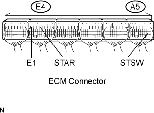
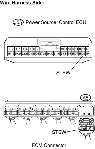
| 9.INSPECT ECM (STAR AND STSW VOLTAGE) |
Measure the voltage of the A5 and E4 ECM connectors while cranking the engine.
- Standard voltage:
Tester Connection
| Specified Condition
|
STAR (E4-4) - E1 (E4-7)
| 9 to 14 V
|
STSW (A5-19) - E1 (E4-7)
| 9 to 14 V
|
- Result:
Terminal STAR
| Terminal STSW
| Proceed to
|
9 to 14 V
| 9 to 14 V
| A
|
0 V
| 9 to 14 V
| B
|
0 V
| 0 V
| C
|
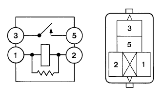
| 10.INSPECT RELAY (ST CUT) |
Remove the ST CUT relay from the engine room J/B and R/B No. 2.
Measure the resistance of the ST CUT relay.
- Standard resistance:
Tester Connection
| Specified Condition
|
3 - 5
| 10 kΩ or higher
|
3 - 5
| Below 1 Ω
(when battery voltage applied to terminals 1 and 2)
|
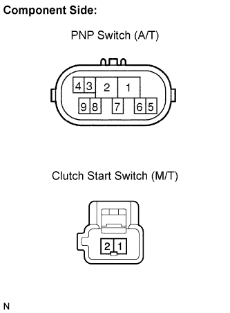
| 11.INSPECT PARK/NEUTRAL POSITION SWITCH (A/T) OR CLUTCH START SWITCH (M/T) |
Disconnect the park/neutral position (PNP) switch (A/T) or clutch switch (M/T) connector.
Measure the resistance between each terminal shown below when the shift lever is moved to each range.
- Standard resistance (A/T):
Shift Position
| Tester Connection
| Specified Condition
|
P
| 4 - 5
| Below 1 Ω
|
N
| 4 - 5
| Below 1 Ω
|
Except N or P
| 4 - 5
| 10 kΩ or higher
|
- Standard resistance (M/T):
Clutch Pedal Operation
| Tester Connection
| Specified Condition
|
Depressed
| 1 - 2
| Below 1 Ω
|
Released
| 1 - 2
| 10 kΩ or higher
|
| | REPLACE PNP SWITCH (A/T) OR CLUTCH START SWITCH (M/T) |
|
|
| OK |
|
|
|
| CHECK AND REPLACE HARNESS AND CONNECTOR (PARK/NEUTRAL POSITION SWITCH - ECM, ECM - ST CUT RELAY, ST) |
|
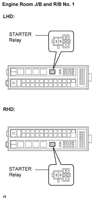
| 12.INSPECT RELAY (STARTER) |
Remove the starter relay from the engine room J/B and R/B No. 1.
Measure the resistance of the starter relay.
- Standard resistance:
Tester Connection
| Specified Condition
|
3 - 5
| 10 kΩ or higher
|
3 - 5
| Below 1 Ω
(when battery voltage applied to terminals 1 and 2)
|
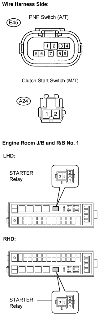
| 13.CHECK HARNESS AND CONNECTOR (PNP SWITCH (A/T) OR CLUTCH START SWITCH (M/T) - ST RELAY) |
Check the harness and the connectors between the park/neutral position switch and the starter relay.
Disconnect the E45*1 or A24*2 switch connector.
*1: A/T
*2: M/T
Remove the starter relay from the engine room J/B and R/B No. 1.
Measure the resistance of the wire harness side connectors.
- Standard resistance (A/T) (Check for open):
Tester Connection
| Specified Condition
|
Park/Neutral position switch (E45-5) - Starter relay (1)
| Below 1 Ω
|
- Standard resistance (M/T) (Check for open):
Tester Connection
| Specified Condition
|
Clutch start switch (A24-2) - Starter relay (1)
| Below 1 Ω
|
- Standard resistance (A/T) (Check for short):
Tester Connection
| Specified Condition
|
Park/Neutral position switch (E45-5) or Starter relay (1) - Body ground
| 10 kΩ or higher
|
- Standard resistance (M/T) (Check for short):
Tester Connection
| Specified Condition
|
Clutch start switch (A24-2) or Starter relay (1) - Body ground
| 10 kΩ or higher
|
Check the harness and the connector between the starter relay and the body ground.
Remove the starter relay from the engine room J/B and R/B No. 1.
Measure the resistance of the starter relay and the body ground.
- Standard resistance (Check for open):
Tester Connection
| Specified Condition
|
Starter relay (2) - Body ground
| Below 1 Ω
|
| | REPAIR OR REPLACE HARNESS OR CONNECTOR |
|
|
| 14.INSPECT ENGINE ROOM RELAY BLOCK (STARTER RELAY VOLTAGE) |
Remove the starter relay from the engine room J/B and R/B No. 1.
Measure the voltage of the engine room J/B and R/B No. 1 and the body ground.
- Standard voltage:
Tester Connection
| Specified Condition
|
Starter relay (5) - Body ground
| 9 to 14 V
|
| | REPAIR OR REPLACE HARNESS OR CONNECTOR |
|
|
| 15.INSPECT STARTER ASSEMBLY |
- HINT:
- Click here.
| | REPAIR OR REPLACE STARTER ASSEMBLY |
|
|
| OK |
|
|
|
| REPAIR OR REPLACE HARNESS OR CONNECTOR (STARTER RELAY - STARTER, STARTER - BATTERY) |
|
| 16.CHECK HARNESS AND CONNECTOR (POWER SOURCE CONTROL ECU - ECM) |
Check the harness and the connectors between the power source control ECU and ECM.
Disconnect the power source control ECU connector.
Disconnect the A5 ECM connector.
Measure the resistance of the wire harness side connectors.
- Standard resistance (Check for open):
Tester Connection
| Specified Condition
|
J55-39 (STSW) - A5-19 (STSW)
| Below 1 Ω
|
- Standard resistance (Check for short):
Tester Connection
| Specified Condition
|
J55-39 (STSW) or A5-19 (STSW) - Body ground
| 10 kΩ or higher
|
| | REPAIR OR REPLACE HARNESS OR CONNECTOR |
|
|
| 17.CHECK AND REPLACE POWER SOURCE CONTROL ECU |
Replace the power source control ECU.
Check the engine cranking function.
A/T Models: When there is fuel in the fuel tank, the key is inside the vehicle and the shift lever is in P, check that depressing the brake pedal and pressing the engine switch crank the engine.
M/T Models: When there is fuel in the tank and the key is inside the vehicle, check that depressing the clutch pedal and the brake pedal and pressing the engine switch crank the engine.
- OK:
- Engine cranks.
- HINT:
- After the power source control ECU is replaced, the engine may not start unless each system is initialized using the above procedure.
| 18.READ VALUE OF INTELLIGENT TESTER (L CODE) |
Reconnect the connectors.
Connect the intelligent tester to the DLC3.
Turn the engine switch on (IG).
Entry & Start:Item
| Measurement Item/Display (Range)
| Normal Condition
| Diagnostic Note
|
L Code Chk
| L code check/ ON or NG
| OK: Normal
NG: Malfunction
| Electrical key in the cabin
|
- OK:
- OK is displayed on the screen.
- HINT:
- If the result of the inspection for a tester display is not as specified, there may be malfunction of the steering lock ECU or the ID code box.
| | GO TO ENGINE IMMOBILISER SYSTEM |
|
|
| 19.READ VALUE OF INTELLIGENT TESTER (ENGINE START REQUEST) |
Connect the intelligent tester to the DLC3.
Turn the engine switch on (IG).
Entry & Start:Item
| Measurement Item/Display (Range)
| Normal Condition
| Diagnostic Note
|
Start Rqst
| Start request signal response/ OK or NG
| OK: Received
NG: Non-received
| -
|
- OK:
- OK (received) and NG (non-received) appear on the screen.
| | REPLACE CERTIFICATION ECU |
|
|
| 20.READ VALUE OF INTELLIGENT TESTER (S CODE) |
Connect the intelligent tester to the DLC3.
Turn the engine switch on (IG).
Entry & Start:Item
| Measurement Item/Display (Range)
| Normal Condition
| Diagnostic Note
|
S Code Chk
| S code check/ OK or NG
| OK: Normal
NG: Malfunction
| -
|
- OK:
- OK is displayed on the screen.
- HINT:
- If the result of the inspection for a tester display is not as specified, there may be malfunction of the certification ECU or the ID code box.
| | GO TO ENGINE IMMOBILISER SYSTEM |
|
|
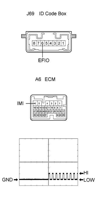
Check the input signal waveform.
Connect the oscilloscope to the terminals J69-6 (EFIO) and A6-6 (IMI).
Turn the engine switch on (IG).
Check the signal waveform according to the condition(s) in the table below.
Item
| Condition
|
Tool setting
| 10 V/DIV., 100 ms./DIV.
|
Vehicle condition
| Engine switch on (IG)
|
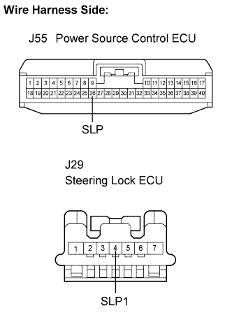
| 22.CHECK WIRE HARNESS (POWER SOURCE CONTROL ECU - STEERING LOCK ECU) |
Disconnect the ECU connector.
Measure the resistance according to the value(s) in the table below.
- Standard resistance:
Tester Connection (Symbols)
| Specified Condition
|
J55-26 (SLP) - J29-4 (SLP1)
| Below 1 Ω
|
J55-26 (SLP) or J29-4 (SLP1) - Body ground
| 10 kΩ or higher
|
| | REPAIR OR REPLACE HARNESS OR CONNECTOR |
|
|
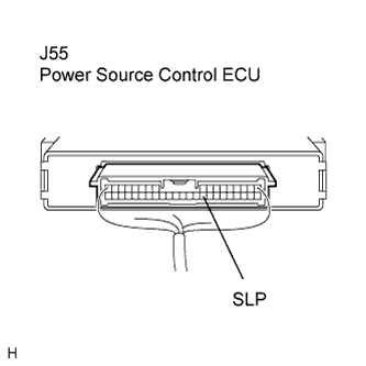
| 23.INSPECT POWER SOURCE CONTROL ECU |
Reconnect the J55 ECU connector.
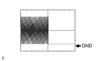
Connect the oscilloscope to the power source control ECU terminals specified in the table below and check the waveform.
Item
| Contents
|
Terminal (Symbols)
| J55-26 (SLP) - Body ground
|
Equipment Setting
| 2 V/DIV., 100 ms./DIV.
|
Condition
| Engine switch on (IG)
|
- OK:
- The waveform appears as shown in the illustration.
| | REPLACE POWER SOURCE CONTROL ECU |
|
|
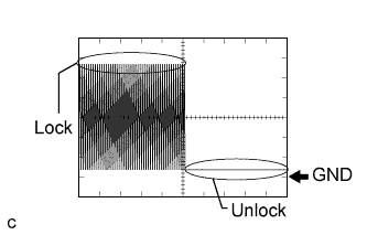
| 24.INSPECT STEERING LOCK ECU |
Reconnect the J29 ECU connector.
Connect the oscilloscope to the power source control ECU terminals specified in the table below and check the waveform.
Item
| Contents
|
Terminal (Symbols)
| J55-26 (SLP) - Body ground
|
Equipment Setting
| 2 V/DIV., 100 ms./DIV.
|
Condition
| Steering is LOCK / UNLOCK
|
- OK:
- The waveform appears as shown in the illustration.
| | REPLACE STEERING LOCK ECU |
|
|
| OK |
|
|
|
| REPLACE POWER SOURCE CONTROL ECU |
|