Dtc B2278 Engine Switch Circuit Malfunction
Engine. Lexus Is250, Is220D. Gse20 Ale20
DESCRIPTION
WIRING DIAGRAM
INSPECTION PROCEDURE
CHECK CONNECTORS
CHECK HARNESS AND CONNECTOR (POWER SOURCE CONTROL ECU -BODY GROUND)
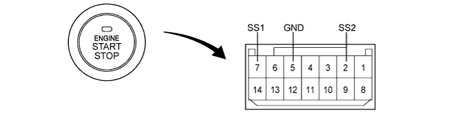
INSPECT ENGINE SWITCH
CHECK WIRE HARNESS (ENGINE SWITCH - POWER SOURCE CONTROL ECU AND BODY GROUND)
READ VALUE OF INTELLIGENT TESTER (START SWITCH 1 AND 2)
RECHECK FOR DTC
DTC B2278 Engine Switch Circuit Malfunction |
DESCRIPTION
This DTC is output when 1) a malfunction is detected between the power source control ECU and the engine switch; or 2) either of the switches inside the engine switch is malfunctioning.- HINT:
- When the power source control ECU is replaced with a new one and the negative (-) battery terminal is connected, the power source mode becomes the IG-ON mode. When the battery is removed and reinstalled, the power source mode that was selected when the battery was removed is restored.
DTC No.
| DTC Detection Condition
| Trouble Area
|
B2278
| Communication is abnormal between the power source control ECU and engine switch or the engine switch is defective
| - Engine switch
- Power source control ECU
- Wire harness or connector
|
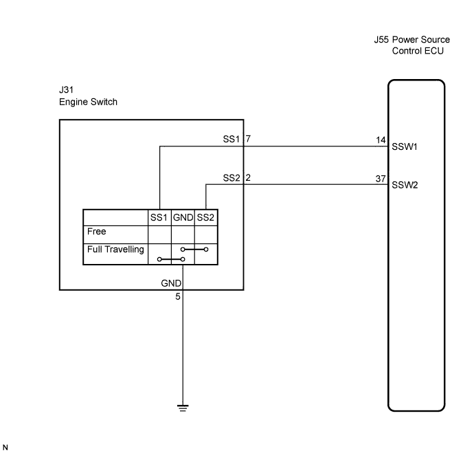
WIRING DIAGRAM
INSPECTION PROCEDURE
Check that the connectors are securely connected and the terminals are not deformed or loose.
- OK:
- The connectors are securely connected and the terminals are not deformed or loose.
| | REPAIR OR REPLACE CONNECTORS |
|
|
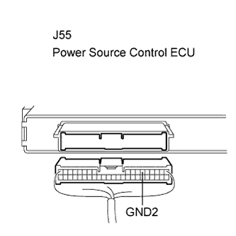
| 2.CHECK HARNESS AND CONNECTOR (POWER SOURCE CONTROL ECU -BODY GROUND) |
Disconnect the J55 ECU connector.
Measure the resistance according to the value(s) in the table below.
- Standard resistance:
Tester Connection (Symbols)
| Condition
| Specified Condition
|
J55-6 (GND2) - Body ground
| Always
| Below 1 Ω
|
| | REPAIR OR REPLACE HARNESS OR CONNECTOR |
|
|
Remove the engine switch.
Disconnect the switch connector.
Measure the resistance according to the value(s) in the table below.
- Standard resistance:
Tester Connection
(Symbols)
| Switch Condition
| Specified Condition
|
7 (SS1) - 5 (GND)
| Pushed
| Below 1 Ω
|
2 (SS2) - 5 (GND)
| Pushed
| Below 1 Ω
|
7 (SS1) - 5 (GND)
| Not pushed
| 10 kΩ or higher
|
2 (SS2) - 5 (GND)
| Not pushed
| 10 kΩ or higher
|
- HINT:
- This switch is a momentary type switch.
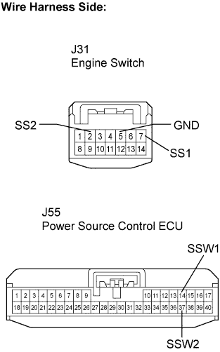
| 4.CHECK WIRE HARNESS (ENGINE SWITCH - POWER SOURCE CONTROL ECU AND BODY GROUND) |
Measure the resistance according to the value(s) in the table below.
- Standard resistance:
Tester Connection (Symbols)
| Condition
| Specified Condition
|
J31-7 (SS1) - J55-14 (SSW1)
| Always
| Below 1 Ω
|
J31-2 (SS2) - J55-37 (SSW2)
| Always
| Below 1 Ω
|
J31-5 (GND) - Body ground
| Always
| Below 1 Ω
|
J31-7 (SS1) or J55-14 (SSW1) - Body ground
| Always
| 10 kΩ or higher
|
J31-2 (SS2) or J55-37 (SSW2) - Body ground
| Always
| 10 kΩ or higher
|
| | REPAIR OR REPLACE HARNESS OR CONNECTOR |
|
|
| 5.READ VALUE OF INTELLIGENT TESTER (START SWITCH 1 AND 2) |
Reconnect the connectors.
Connect the intelligent tester to the DLC3.
Turn the engine switch on (IG).
Check the DATA LIST for proper functioning of the start switches 1 and 2.
Power Source Control:Item
| Measurement Item/Display (Range)
| Normal Condition
| Diagnostic Note
|
St SW1
| Start Switch 1/ ON or OFF
| ON: Engine switch on (IG)
OFF: Engine switch OFF
| -
|
St SW2
| Start Switch 2/ ON or OFF
| ON: Engine switch on (IG)
OFF: Engine switch OFF
| -
|
- OK:
- ON (engine switch on (IG)) and OFF (engine switch off) appear on the screen.
| | REPLACE POWER SOURCE CONTROL ECU |
|
|
Delete the DTCs (Click here).
Check for DTCs again.
- OK:
- DTC B2278 is not output.
| | REPLACE POWER SOURCE CONTROL ECU |
|
|
| OK |
|
|
|
| CHECK INTERMITTENT PROBLEMS |
|