Body Electrical. Lexus Is250, Is220D. Gse20 Ale20
Door Lock. Lexus Is250, Is220D. Gse20 Ale20
Entry And Start System -- Terminals Of Ecu |
| CHECK CERTIFICATION ECU |

Disconnect the P33 ECU connector.
Measure the voltage and resistance according to the value(s) in the table below.
Symbols (Terminal No.) Wiring Color Terminal Description Condition Specified Condition +B1 (P33-1) - Body ground L - Body ground +B power supply Always 10 to 14 V IG (P33-18) - Body ground B - Body ground Ignition power supply Engine switch off Below 1 V IG (P33-18) - Body ground B - Body ground Ignition power supply Engine switch on (IG) 10 to 14 V E (P33-17) - Body ground W-B - Body ground Ground Always Below 1 Ω ACC (P33-19) - Body ground O - Body ground ACC power supply Engine switch off Below 1 V ACC (P33-19) - Body ground O - Body ground ACC power supply Engine switch on (ACC) 10 to 14 V TSW1 (P33-3) - Body ground Y - Body ground Entry lock switch signal Front lock switch LH not pushed 10 KΩ or higher TSW1 (P33-3) - Body ground Y - Body ground Entry lock switch signal Front lock switch LH pushed Below 1 Ω TSW2 (P33-4) - Body ground BR - Body ground Entry lock switch signal Front lock switch RH not pushed 10 KΩ or higher TSW2 (P33-4) - Body ground BR - Body ground Entry lock switch signal Front lock switch RH pushed Below 1 Ω LIN (P33-10) - Body ground V - Body ground LIN line Always 10 kΩ or higher MPX1 (P33-27) - Body ground GR - Body ground MPX line Always 10 kΩ or higher MPX2 (P33-28) - Body ground GR - Body ground MPX line Always 10 kΩ or higher AGND (P33-40) - Body ground LG - Body ground Ground Always Below 1 Ω - If the result is not as specified, the wire harness side may have a malfunction.
- If the result is not as specified, the wire harness side may have a malfunction.
Reconnect the P33 ECU connector.
Measure the voltage according to the value(s) in the table below.
*1: LHD ModelsSymbols (Terminal No.) Wiring Color Terminal Description Condition Specified Condition CLG1 (P33-33) - CG1B (P33-34) R - BR Door electrical key oscillator (front LH) sensor signal All doors closed, all doors locked and engine switch off Alternating between 5 V and below 1 V CLG1 (P33-33) - CG1B (P33-34) R - BR Door electrical key oscillator (front LH) sensor signal Door unlocked or door open Below 1 V SEN1 (P33-22) - E (P33-17) W (*1) - W-B
G (*2) - W-BTouch sensor detection signal Outside door handle touched Below 1 V SEN1 (P33-22) - E (P33-17) W (*1) - W-B
G (*2) - W-BTouch sensor detection signal Outside door handle not touched 10 to 14 V SEL1 (P33-5) - E (P33-17) W (*1) - W-B
B (*2) - W-BTouch sensor activation control signal Move the key more than 5 m (16.4 ft) away from the front door LH 10 to 14 V SEL1 (P33-5) - E (P33-17) W (*1) - W-B
B (*2) - W-BTouch sensor activation control signal Bring it to the outside handle Below 1 V CLG2 (P33-35) - CG2B (P33-36) G - BR Door electrical key oscillator (front RH) sensor signal All doors closed, all doors locked and engine switch off Alternating between 5 V and below 1 V CLG2 (P33-35) - CG2B (P33-36) G - BR Door electrical key oscillator (front RH) sensor signal Door unlocked or door open Below 1 V SEN2 (P33-23) - E (P33-17) W (*1) - W-B
G (*2) - W-BTouch sensor detection signal Outside door handle touched Below 1 V SEN2 (P33-23) - E (P33-17) W (*1) - W-B
G (*2) - W-BTouch sensor detection signal Outside door handle not touched 10 to 14 V SEL2 (P33-6) - E (P33-17) W (*1) - W-B
B (*2) - W-BTouch sensor activation control signal Move the key more than 5 m (16.4 ft) away from the front door RH 10 to 14 V SEL2 (P33-6) - E (P33-17) W (*1) - W-B
B (*2) - W-BTouch sensor activation control signal Bring it to the outside handle Below 1 V CLG5 (P33-11) - CG5B (P33-12) Y - V Indoor electrical key oscillator (front) sensor signal 30 seconds after driver side door opened and closed, engine switch off Alternating between 5 V and below 1 V CLG5 (P33-11) - CG5B (P33-12) Y - V Indoor electrical key oscillator (front) sensor signal Within 30 seconds driver side door opened and closed, engine switch off Below 1 V CLG6 (P33-13) - CG6B (P33-14) LG - O Indoor electrical key oscillator (rear) sensor signal 30 seconds after driver side door opened and closed, engine switch off Alternating between 5 V and below 1 V CLG6 (P33-13) - CG6B (P33-14) LG - O Indoor electrical key oscillator (rear) sensor signal Within 30 seconds driver side door opened and closed, engine switch off Below 1 V CLG7 (P33-15) - CG7B (P33-16) SB - P Luggage electrical key oscillator (inner) sensor signal Luggage compartment door opening switch OFF Alternating between 5 V and below 1 V CLG7 (P33-15) - CG7B (P33-16) SB - P Luggage electrical key oscillator (inner) sensor signal Luggage compartment door opening switch ON Below 1 V CLG8 (P33-31) - CG8B (P33-32) B - W Luggage electrical key oscillator (outer) sensor signal Luggage compartment door opening switch OFF Alternating between 5 V and below 1 V CLG8 (P33-31) - CG8B (P33-32) B - W Luggage electrical key oscillator (outer) sensor signal Luggage compartment door opening switch ON Below 1 V RCO (P33-29) - E (P33-17) LG - W-B Entry door control receiver power source Engine switch off, all doors closed and electrical key switch on. 4.6 to 5.4 V RCO (P33-29) - E (P33-17) LG - W-B Entry door control receiver power source Engine switch off, all doors closed and electrical key switch off. Below 1 V RSSI (P33-39) - E (P33-17) Y - W-B Entry door control receiver electric wave existence signal Engine switch off, all doors closed, the electrical key is not in the action area. 10 to 14 V RSSI (P33-39) - E (P33-17) Y - W-B Entry door control receiver electric wave existence signal Engine switch off, all doors closed, the electrical key is in the action area. Below 1 V RDA (P33-38) - E (P33-17) R - W-B Entry door control receiver data input signal Engine switch off, all doors closed and electrical key switch off. 10 to 14 V RDA (P33-38) - E (P33-17) R - W-B Entry door control receiver data input signal Engine switch off, all doors closed and electrical key switch on. Pulse generation RDA (P33-38) - Body ground R - Body ground Tuner input signal Engine switch off, all doors closed, the electrical key is not in the action area. 10 to 14 V RDA (P33-38) - Body ground R - Body ground Tuner input signal The electrical key is in the action area. Pulse generation ASEL (P33-37) - Body ground SB - Body ground Tuner select signal Engine switch off, luggage compartment door closed. 4.6 to 5.4 V ASEL (P33-37) - Body ground SB - Body ground Tuner select signal Engine switch off, luggage compartment door open. Below 1 V VC5 (P33-30) - Body ground L - Body ground Transponder key amplifier power supply Electrical key is not in the vehicle. Below 1 V VC5 (P33-30) - Body ground L - Body ground Transponder key amplifier power supply Have the electrical key outside the cabin and open the driver's door. 4.6 to 5.4 V TXCT (P33-8) - Body ground G - Body ground Transponder key amplifier output signal Electrical key is not in the cabin. Below 1 V TXCT (P33-8) - Body ground G - Body ground Transponder key amplifier output signal Have the electrical key outside the cabin and open the driver's door. Pulse generation
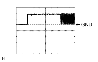
(see waveform 1)CODE (P33-9) - Body ground GR - Body ground Transponder key amplifier communication signal Electrical key is not in the cabin. Below 1 V CODE (P33-9) - Body ground GR - Body ground Transponder key amplifier communication signal Have the electrical key outside the cabin and open the driver's door. Pulse generation
(see waveform 2)
*2: RHD Models
If the result is not as specified, the ECU may have a malfunction.Inspect using an oscilloscope.
Waveform 1 (Reference): Terminal TXCT - Body ground Tool Setting 2 V/DIV, 10 ms/DIV Condition The electrical key is not in the cabin. Inspect using an oscilloscope.
Waveform 2 (Reference): Terminal CODE - Body ground Tool Setting 2 V/DIV, 20 ms/DIV Condition The electrical key is not in the cabin.
 |
 |
| MAIN BODY ECU LH (COWL SIDE JUNCTION BLOCK LH) |
Measure the voltage according to the value(s) in the table below.
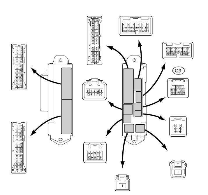
If the result is not as specified, the junction block may have a malfunction.Symbols (Terminal No.) Wiring Color Terminal Description Condition Specified Condition LPSW (Q3-13) - Body ground BR - Body ground Luggage compartment opener switch signal Luggage compartment opener switch OFF 10 to 14 V LPSW (Q3-13) - Body ground BR - Body ground Luggage compartment opener switch signal Luggage compartment opener switch ON Below 1 V