Dtc C1267/67 Brake Pedal Load Sensing Switch
Brake. Lexus Is250, Is220D. Gse20 Ale20
DESCRIPTION
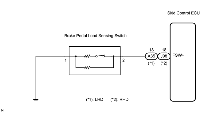
WIRING DIAGRAM
INSPECTION PROCEDURE
READ VALUE OF INTELLIGENT TESTER (BRAKE PEDAL LOAD SENSING SWITCH)
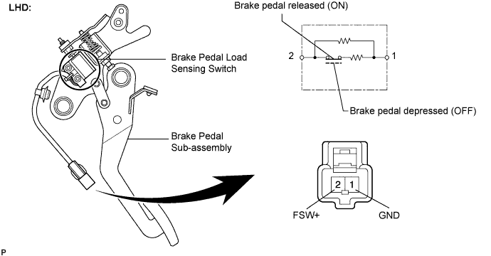
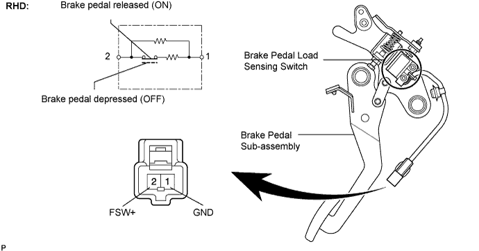
INSPECT BRAKE PEDAL LOAD SENSING SWITCH
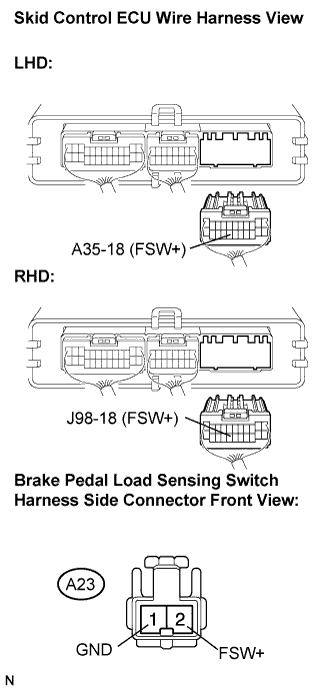
CHECK HARNESS AND CONNECTOR (SKID CONTROL ECU - BRAKE PEDAL LOAD SENSING SWITCH)
RECONFIRM DTC
DTC C1267/67 Brake Pedal Load Sensing Switch |
DESCRIPTION
The brake pedal load sensing switch is turned on when the brake pedal is depressed with force exceeding a predetermined level.The skid control ECU detects if the brake pedal is depressed or not via this circuit.DTC No.
| DTC Detection Condition
| Trouble Area
|
C1267/67
| When any of the following is detected:
- An open or short in the brake pedal load sensing switch continues for 0.3 seconds or more.
- Immediately after the engine switch is turned on (IG), the brake pedal load sensing switch is ON and the stop light switch is OFF for 10 seconds or more.
- While the vehicle speed changes from 0 mph (0 km/h) to 18 mph (30 km/h), the condition that the brake pedal load sensing switch remains ON occurs 5 times in succession.
- With the stop light switch ON, the brake pedal load sensing switch OFF, and the master cylinder pressure 6 Mpa or more, the deceleration is 0.4 G or more for 1 second or more.
- With the stop light switch ON, the brake pedal load sensing switch OFF, and the master cylinder pressure 6 Mpa or more, the vehicle speed is 0 mph (0 km/h) for 5 seconds or more.
| - Brake pedal load sensing switch
- Brake pedal load sensing switch circuit
|
WIRING DIAGRAM
INSPECTION PROCEDURE
- NOTICE:
- When replacing the skid control ECU, perform zero point calibration and store system information (Click here).
- HINT:
- If C1249/49 is output, repair it before repairing C1267/67 based on the flow chart below.
| 1.READ VALUE OF INTELLIGENT TESTER (BRAKE PEDAL LOAD SENSING SWITCH) |
Connect the intelligent tester to the DLC3.
Start the engine.
Select the Data List mode on the intelligent tester.
ABS / VSC:Item (Display)
| Measurement Item / Range (Display)
| Normal Condition
|
Brake Pedal Load Sensing SW
| Brake pedal load sensing switch / ON or OFF
| ON : Brake pedal depressed
OFF : Brake pedal released
|
Read the value of the brake pedal load sensing switch displayed on the intelligent tester when depressing and releasing the brake pedal.
- OK:
Condition
| Display
|
Brake pedal depressed
| ON
|
Brake pedal released
| OFF
|
| 2.INSPECT BRAKE PEDAL LOAD SENSING SWITCH |
- NOTICE:
- Do not remove the brake pedal load sensing switch from the brake pedal sub-assembly.
- When there is a malfunction in the brake pedal load sensing switch, replace the brake pedal sub-assembly.
Turn the engine switch off.
Disconnect the brake pedal load sensing switch connector.
Measure the resistance according to the value(s) in the table below.
- Standard resistance:
Tester Connection
| Condition
| Specified Condition
|
2 (FSW+) - 1 (GND)
| Brake pedal depressed (OFF)
| 0.9 to 1.1 kΩ
|
2 (FSW+) - 1 (GND)
| Brake pedal released (ON)
| 192 to 234 Ω
|
| | REPLACE BRAKE PEDAL SUB-ASSEMBLY (BRAKE PEDAL LOAD SENSING SWITCH) |
|
|
| 3.CHECK HARNESS AND CONNECTOR (SKID CONTROL ECU - BRAKE PEDAL LOAD SENSING SWITCH) |
Disconnect the skid control ECU connector.
Measure the resistance according to the value(s) in the table below.
- Standard resistance:
- LHD:
Tester Connection
| Condition
| Specified Condition
|
A35-18 (FSW+) - A23-2 (FSW+)
| Always
| Below 1 Ω
|
A35-18 (FSW+) - Body ground
| Always
| 10 kΩ or higher
|
A23-1 (GND) - Body ground
| Always
| Below 1 Ω
|
- RHD:
Tester Connection
| Condition
| Specified Condition
|
J98-18 (FSW+) - A23-2 (FSW+)
| Always
| Below 1 Ω
|
J98-18 (FSW+) - Body ground
| Always
| 10 kΩ or higher
|
A23-1 (GND) - Body ground
| Always
| Below 1 Ω
|
| | REPAIR OR REPLACE HARNESS OR CONNECTOR |
|
|
Reconnect the skid control ECU connector and the brake pedal load sensing switch connector.
Clear the DTC (Click here).
Check if the same DTC is recorded (Click here).
- Result:
Condition
| Proceed to
|
DTC (C1267/67) is not output
| A
|
DTC (C1267/67) is output
| B
|
| A |
|
|
|
| USE SIMULATION METHOD TO CHECK |
|