Dtc C1246/46 Master Cylinder Pressure Sensor Malfunction
Brake. Lexus Is250, Is220D. Gse20 Ale20
DESCRIPTION
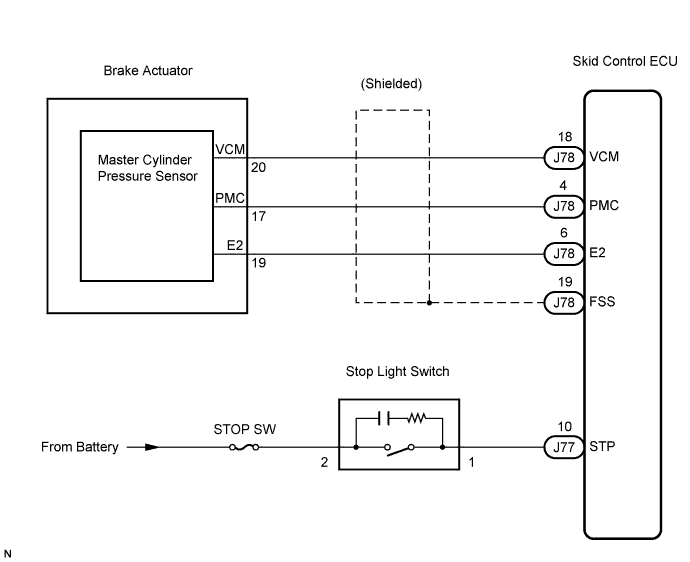
WIRING DIAGRAM
INSPECTION PROCEDURE
CHECK STOP LIGHT OPERATION
READ VALUE OF INTELLIGENT TESTER (STOP LIGHT SWITCH)
INSPECT SKID CONTROL ECU (STP TERMINAL)
READ VALUE OF INTELLIGENT TESTER (MASTER CYLINDER PRESSURE SENSOR)
CHECK HARNESS AND CONNECTOR (SKID CONTROL ECU - BRAKE ACTUATOR ASSEMBLY)
INSPECT SKID CONTROL ECU (SENSOR INPUT)
INSPECT SKID CONTROL ECU (SENSOR OUTPUT)
RECONFIRM DTC
DTC C1246/46 Master Cylinder Pressure Sensor Malfunction |
DTC C1281/81 Master Cylinder Pressure Sensor Output Malfunction (Test Mode DTC) |
DESCRIPTION
The master cylinder pressure sensor is built into the brake actuator assembly.DTC C1281/81 can be deleted when the master cylinder pressure sensor sends a master cylinder pressure signal or the Test Mode ends. DTC C1281/81 is output only in the Test Mode.DTC No.
| DTC Detection Condition
| Trouble Area
|
C1246/46
| When any of the following is detected:
- At a vehicle speed of 4.3 mph (7 km/h) or more, when the PMC terminal voltage is over 0.86 V, it does not change by 0.005 V or more for 30 seconds.
- Noise occurs in the PMC terminal 7 times or more within 5 seconds.
- When the stop light switch is OFF, the PMC terminal voltage is more than 0.86 V or less than 0.3 V for 5 seconds or more.
- With the IG1 terminal voltage between 9.5 and 17.2 V, the VCM terminal voltage is not between 4.4 and 5.6 V for 1.2 seconds or more.
- When the VCM terminal voltage is between 4.4 and 5.6 V, the PCM terminal voltage is not between 0.14 and 4.85 V for 1.2 seconds or more.
| - Master cylinder pressure sensor
- Master cylinder pressure sensor circuit
- Stop light switch circuit
- Skid control ECU
|
WIRING DIAGRAM
INSPECTION PROCEDURE
- NOTICE:
- When replacing the skid control ECU, perform zero point calibration and store system information (Click here).
| 1.CHECK STOP LIGHT OPERATION |
Check that the stop light comes on when the brake pedal is depressed, and goes off when the brake pedal is released.
- OK:
Condition
| Illumination Condition
|
Brake pedal depressed
| ON
|
Brake pedal released
| OFF
|
| | INSPECT STOP LIGHT CIRCUIT |
|
|
| 2.READ VALUE OF INTELLIGENT TESTER (STOP LIGHT SWITCH) |
Connect the intelligent tester to the DLC3.
Start the engine.
Select the Data List mode on the intelligent tester.
ABS / VSC:Item (Display)
| Measurement Item / Range (Display)
| Normal Condition
|
Stop Lamp SW
| Stop light switch / ON or OFF
| ON: Brake pedal depressed
OFF: Brake pedal released
|
Check that the stop light display on the intelligent tester changes when the brake pedal is depressed.
- OK:
- When the brake pedal is depressed, the intelligent tester displays "ON".
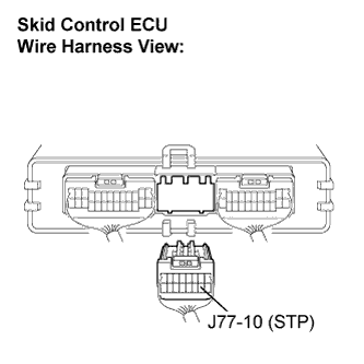
| 3.INSPECT SKID CONTROL ECU (STP TERMINAL) |
Disconnect the skid control ECU connector.
Measure the voltage according to the value(s) in the table below.
- Standard voltage:
Tester Connection
| Condition
| Specified Condition
|
J77-10 (STP) - Body ground
| Stop light switch ON (Brake pedal depressed)
| 8 to 14 V
|
J77-10 (STP) - Body ground
| Stop light switch OFF (Brake pedal released)
| Below 1.5 V
|
| | REPAIR OR REPLACE HARNESS OR CONNECTOR (STP CIRCUIT) |
|
|
| 4.READ VALUE OF INTELLIGENT TESTER (MASTER CYLINDER PRESSURE SENSOR) |
Select the Data List mode on the intelligent tester.
ABS / VSC:Item (Display)
| Measurement Item / Range (Display)
| Normal Condition
|
Master Cylinder Sensor
| Master cylinder pressure sensor 1 reading / min.: 0 V, max.: 5 V
| When brake pedal is released: 0.3 to 0.9 V
|
Check that the brake fluid pressure value of the master cylinder pressure sensor on the intelligent tester changes when the brake pedal is depressed.
- OK:
- When the pedal is depressed, voltage displayed on the intelligent tester increases.
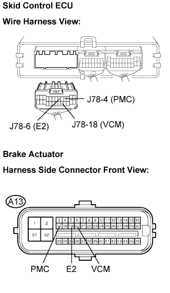
| 5.CHECK HARNESS AND CONNECTOR (SKID CONTROL ECU - BRAKE ACTUATOR ASSEMBLY) |
Turn the engine switch off.
Disconnect the skid control ECU connector and the brake actuator connector.
Measure the resistance according to the value(s) in the table below.
- Standard resistance:
Tester Connection
| Condition
| Specified Condition
|
J78-18 (VCM) - A13-20 (VCM)
| Always
| Below 1 Ω
|
J78-18 (VCM) - Body ground
| Always
| 10 kΩ or higher
|
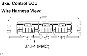
J78-4 (PMC) - A13-17 (PMC)
| Always
| Below 1 Ω
|
J78-4 (PMC) - Body ground
| Always
| 10 kΩ or higher
|
J78-6 (E2) - A13-19 (E2)
| Always
| Below 1 Ω
|
J78-6 (E2) - Body ground
| Always
| 10 kΩ or higher
|
| | REPAIR OR REPLACE HARNESS OR CONNECTOR |
|
|
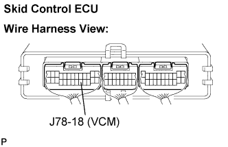
| 6.INSPECT SKID CONTROL ECU (SENSOR INPUT) |
Reconnect the skid control ECU connector.
Turn the engine switch on (IG).
Measure the voltage according to the value(s) in the table below.
- Standard voltage:
Tester Connection
| Condition
| Specified Condition
|
J78-18 (VCM) - Body ground
| Engine switch on (IG)
| 4.5 to 5.5 V
|
| 7.INSPECT SKID CONTROL ECU (SENSOR OUTPUT) |
Reconnect the brake actuator connector.
Remove either the right or left front brake cylinder bleeder plug.
Install the pressure gauge via the attachment, and bleed the gauge of air (Click here).
Measure the voltage according to the value(s) in the table below.
- Standard voltage:
Tester Connection
| Fluid Pressure MPa (kgf/cm2, psi)
| Specified Condition
|
J78-4 (PMC) - Body ground
| 0 (0, 0)
| 0.37 to 0.63 V
|
J78-4 (PMC) - Body ground
| 5.88 (60, 853)
| 1.57 to 1.83 V
|
J78-4 (PMC) - Body ground
| 11.8 (120, 1,707)
| 2.77 to 3.03 V
|
| | REPLACE BRAKE ACTUATOR ASSEMBLY |
|
|
Turn the engine switch off.
Clear the DTC (Click here).
Start the engine.
At a speed of 18 mph (30 km/h) or more, drive the vehicle and perform braking test (decelerate the vehicle by depressing the brake pedal).
Check if the same DTC is recorded (Click here).
- Result:
Condition
| Proceed to
|
DTC (C1246/46) is not output
| A
|
DTC (C1246/46) is output
| B
|
| A |
|
|
|
| USE SIMULATION METHOD TO CHECK |
|