Brake. Lexus Is250, Is220D. Gse20 Ale20
DESCRIPTION
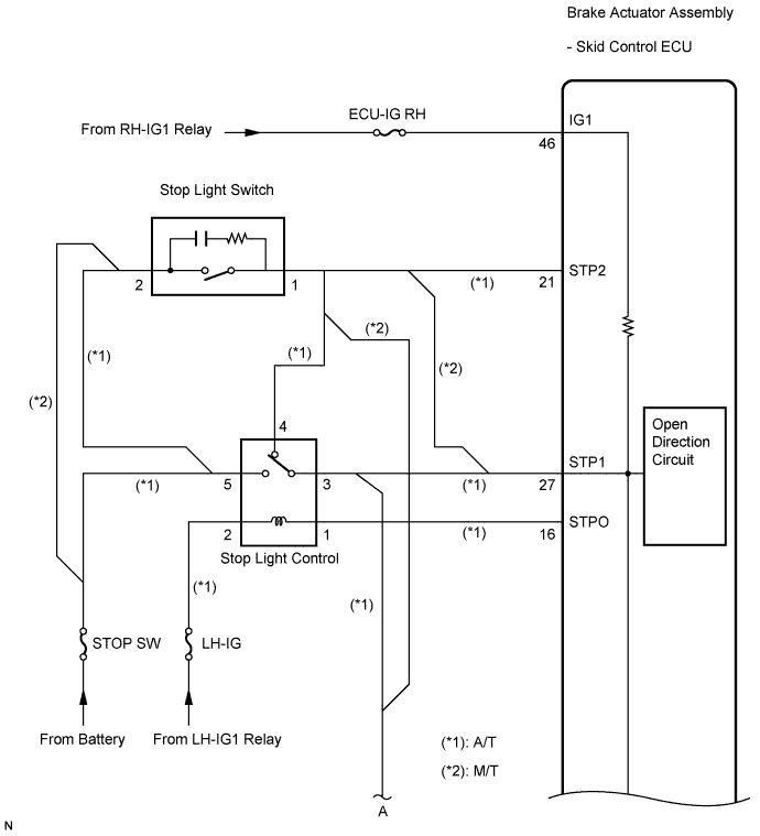
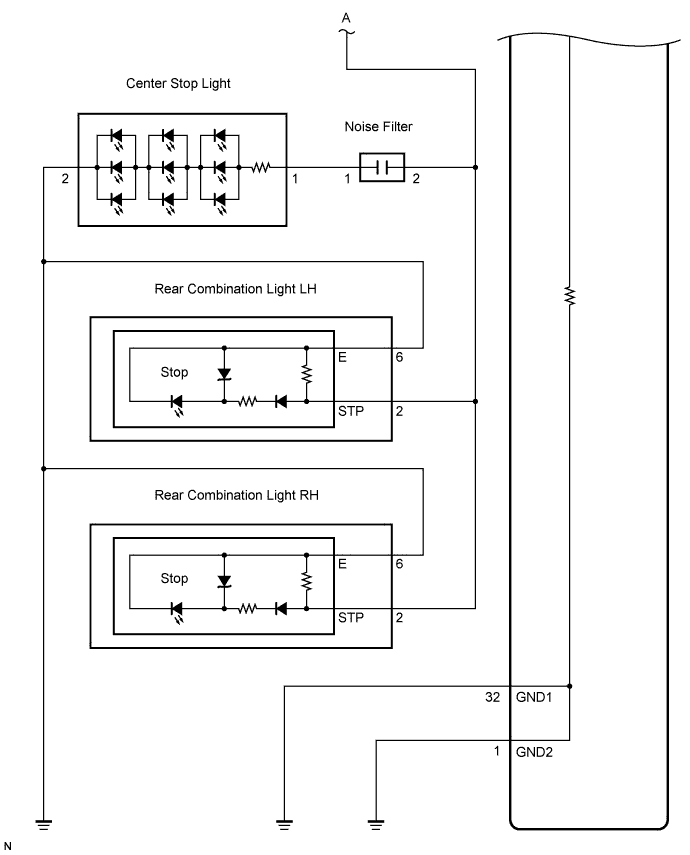
WIRING DIAGRAM
INSPECTION PROCEDURE
INSPECT STOP SW FUSE
CHECK STOP LIGHT OPERATION
INSPECT SKID CONTROL ECU (STP1 TERMINAL)
INSPECT SKID CONTROL ECU (IG1 AND GND TERMINAL)
READ VALUE OF INTELLIGENT TESTER (STOP LIGHT SWITCH AND BRAKE PEDAL LOAD SENSING SWITCH)
RECONFIRM DTC
CHECK BRAKE PEDAL AND STOP LIGHT SWITCH INSTALLATION
RECONFIRM DTC
INSPECT STOP LIGHT SWITCH (POWER SOURCE TERMINAL)
INSPECT STOP LIGHT SWITCH
INSPECT STOP LIGHT CONTROL RELAY
CHECK HARNESS AND CONNECTOR (STOP LIGHT SWITCH - ENGINE ROOM NO. 2 RELAY BLOCK)
CHECK HARNESS AND CONNECTOR (SKID CONTROL ECU - ENGINE ROOM NO. 2 RELAY BLOCK)
RECONFIRM DTC
CHECK HARNESS AND CONNECTOR (SKID CONTROL ECU - STOP LIGHT SWITCH)
RECONFIRM DTC
DTC C1249/49 Open in Stop Light Switch Circuit |
DESCRIPTION
The skid control ECU (housed in the actuator assembly) inputs the stop light switch signal and the condition of brake operation.The skid control ECU has an open detection circuit, which outputs this DTC when detecting an open in the stop light input line while the stop light switch is OFF.DTC No.
| DTC Detection Condition
| Trouble Area
|
C1249/49
| - When IG1 terminal voltage is 9.5 to 17.2 V, an open circuit of the stop light switch continues for 0.3 seconds or more.
- When the brake pedal load sensing switch is ON, the master cylinder pressure is 2 Mpa or more and the deceleration calculated from the vehicle speed is 0.2 G or more, the stop light switch is OFF for 2 seconds or more.
| - STOP SW fuse
- Stop light switch
- Stop light switch circuit
- Stop light control relay (A/T)
- Stop light control relay circuit (A/T)
- Brake actuator assembly (Skid control ECU)
|
WIRING DIAGRAM
INSPECTION PROCEDURE
- NOTICE:
- When replacing the brake actuator assembly, perform zero point calibration (Click here).
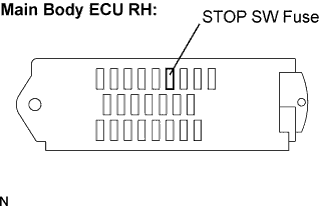
Remove the STOP SW fuse from the main body ECU RH.
Measure the resistance according to the value(s) in the table below.
- Standard resistance:
Tester Connection
| Condition
| Specified Condition
|
STOP SW (7.5A) fuse
| Always
| Below 1 Ω
|
| 2.CHECK STOP LIGHT OPERATION |
Install the STOP SW fuse.
Check that the stop light comes on when the brake pedal is depressed, and goes off when the brake pedal is released.
- OK:
Condition
| Illumination Condition
|
Brake pedal depressed
| ON
|
Brake pedal released
| OFF
|
| 3.INSPECT SKID CONTROL ECU (STP1 TERMINAL) |
Disconnect the skid control ECU connector.
Measure the voltage according to the value(s) in the table below.
- Standard voltage:
Tester Connection
| Condition
| Specified Condition
|
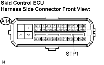
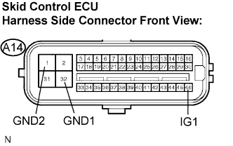
A14-27 (STP1) - Body ground
| Stop light switch ON (Brake pedal depressed)
| 8 to 14 V
|
A14-27 (STP1) - Body ground
| Stop light switch OFF (Brake pedal released)
| Below 1.5 V
|
| | REPAIR OR REPLACE HARNESS OR CONNECTOR (STP1 CIRCUIT) |
|
|
| 4.INSPECT SKID CONTROL ECU (IG1 AND GND TERMINAL) |
Turn the engine switch on (IG).
Measure the voltage according to the value(s) in the table below.
- Standard voltage:
Tester Connection
| Condition
| Specified Condition
|
A14-46 (IG1) - Body ground
| Engine switch on (IG)
| 10 to 14 V
|
Turn the engine switch off.
Measure the resistance according to the value(s) in the table below.
- Standard resistance:
Tester Connection
| Condition
| Specified Condition
|
A14-32 (GND1) - Body ground
| Always
| Below 1 Ω
|
A14-1 (GND2) - Body ground
| Always
| Below 1 Ω
|
| | REPAIR OR REPLACE HARNESS OR CONNECTOR (IG1 OR GND CIRCUIT) |
|
|
| 5.READ VALUE OF INTELLIGENT TESTER (STOP LIGHT SWITCH AND BRAKE PEDAL LOAD SENSING SWITCH) |
Reconnect the skid control ECU connector.
Connect the intelligent tester to the DLC3.
Start the engine.
Select the Data List mode on the intelligent tester.
ABS / VSC:Item (Display)
| Measurement Item / Range (Display)
| Normal Condition
|
Stop Lamp SW
| Stop light switch / ON or OFF
| ON: Brake pedal depressed
OFF: Brake pedal released
|
Brake Pedal Load Sensing SW
| Brake pedal load sensing switch / ON or OFF
| ON: Brake pedal depressed
OFF: Brake pedal released
|
Check that the stop light display observed on the intelligent tester changes when the brake pedal is depressed.
- OK:
- When the brake pedal is depressed, the intelligent tester displays "ON".
Slowly depress the brake pedal, and check when the stop light switch and brake pedal load sensing switch turn ON.
- OK:
- First the stop light switch should turn ON, and then the brake pedal load sensing switch should turn ON.
- Result:
Condition
| Proceed to
|
OK
| A
|
NG (The turning on of the stop light switch is not confirmed)
| B
|
NG (The brake pedal load sensing switch turns on first)
| C
|
| | REPLACE BRAKE ACTUATOR ASSEMBLY |
|
|
| |
|
Clear the DTC (Click here).
Start the engine.
Depress the brake pedal several times to test the stop light circuit.
Check if the same DTC is recorded (Click here).
- Result:
Condition
| Proceed to
|
DTC (C1249/49) is not output
| A
|
DTC (C1249/49) is output
| B
|
- HINT:
- If troubleshooting has been carried out according to the Problem Symptoms Table, refer back to the table and proceed to the next step (Click here).
| | REPLACE BRAKE ACTUATOR ASSEMBLY |
|
|
| A |
|
|
|
| USE SIMULATION METHOD TO CHECK |
|
| 7.CHECK BRAKE PEDAL AND STOP LIGHT SWITCH INSTALLATION |
Check the brake pedal height and stop light switch installation (Click here).
- OK:
- The brake pedal and stop light switch are normal.
| | ADJUST BRAKE PEDAL OR STOP LIGHT SWITCH |
|
|
Clear the DTC (Click here).
Start the engine.
Depress the brake pedal several times to test the stop light circuit.
Check if the same DTC is recorded (Click here).
- Result:
Condition
| Proceed to
|
DTC (C1249/49) is not output
| A
|
DTC (C1249/49) is output
| B
|
- HINT:
- If troubleshooting has been carried out according to the Problem Symptoms Table, refer back to the table and proceed to the next step (Click here).
| | REPLACE BRAKE PEDAL SUB-ASSEMBLY (BRAKE PEDAL LOAD SENSING SWITCH) |
|
|
| A |
|
|
|
| USE SIMULATION METHOD TO CHECK |
|
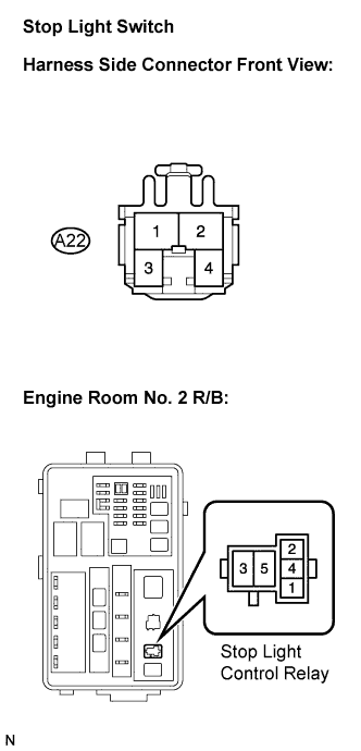
| 9.INSPECT STOP LIGHT SWITCH (POWER SOURCE TERMINAL) |
Disconnect the stop light switch connector.
Measure the voltage according to the value(s) in the table below.
- Standard voltage:
Tester Connection
| Condition
| Specified Condition
|
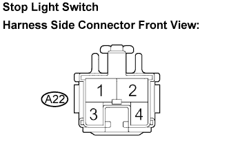
A22-2 - Body ground
| Always
| 10 to 14 V
|
| | REPAIR OR REPLACE HARNESS OR CONNECTOR (POWER SOURCE CIRCUIT) |
|
|
| 10.INSPECT STOP LIGHT SWITCH |
Measure the resistance according to the value(s) in the table below.
- Standard resistance:
Tester Connection
| Condition
| Specified Condition
|
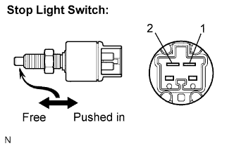
1 - 2
| Switch pin free
| Below 1 Ω
|
1 - 2
| Switch pin pushed in
| 10 kΩ or higher
|
- Result:
Result
| Proceed to
|
OK (for A/T)
| A
|
OK (for M/T)
| B
|
NG
| C
|
| |
|
| | REPLACE STOP LIGHT SWITCH |
|
|
| 11.INSPECT STOP LIGHT CONTROL RELAY |
Remove the stop light control relay.
Measure the resistance according to the value(s) in the table below.
- Standard resistance:
Tester Connection
| Condition
| Specified Condition
|
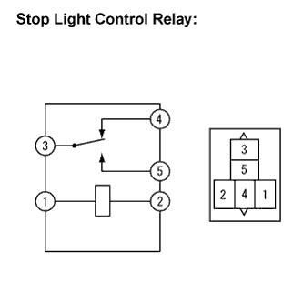
3 - 4
| Always
| Below 1 Ω
|
| | REPLACE STOP LIGHT CONTROL RELAY |
|
|
| 12.CHECK HARNESS AND CONNECTOR (STOP LIGHT SWITCH - ENGINE ROOM NO. 2 RELAY BLOCK) |
Measure the resistance according to the value(s) in the table below.
- Standard resistance:
Tester Connection
| Condition
| Specified Condition
|
A22-1 - Stop light control relay terminal 4
| Always
| Below 1 Ω
|
A22-1 - Body ground
| Always
| 10 kΩ or higher
|
| | REPAIR OR REPLACE HARNESS OR CONNECTOR |
|
|
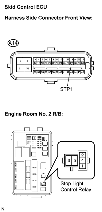
| 13.CHECK HARNESS AND CONNECTOR (SKID CONTROL ECU - ENGINE ROOM NO. 2 RELAY BLOCK) |
Disconnect the skid control ECU connector.
Measure the resistance according to the value(s) in the table below.
- Standard resistance:
Tester Connection
| Condition
| Specified Condition
|
A14-27 (STP1) - Stop light control relay terminal 3
| Always
| Below 1 Ω
|
A14-27 (STP1) - Body ground
| Always
| 10 kΩ or higher
|
| | REPAIR OR REPLACE HARNESS OR CONNECTOR |
|
|
Clear the DTC (Click here).
Start the engine.
Depress the brake pedal several times to test the stop light circuit.
Check if the same DTC is recorded (Click here).
- HINT:
- Reinstall the relay, connectors, etc. and restore the vehicle to its prior condition before rechecking for DTCs.
- Result:
Condition
| Proceed to
|
DTC (C1249/49) is not output
| A
|
DTC (C1249/49) is output
| B
|
- HINT:
- If troubleshooting has been carried out according to the Problem Symptoms Table, refer back to the table and proceed to the next step (Click here).
| | REPLACE BRAKE ACTUATOR ASSEMBLY |
|
|
| A |
|
|
|
| INSPECT LIGHTING SYSTEM (STOP LIGHT CIRCUIT) |
|
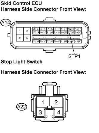
| 15.CHECK HARNESS AND CONNECTOR (SKID CONTROL ECU - STOP LIGHT SWITCH) |
Disconnect the skid control ECU connector.
Measure the resistance according to the value(s) in the table below.
- Standard resistance:
Tester Connection
| Condition
| Specified Condition
|
A14-27 (STP1) - A22-1
| Always
| Below 1 Ω
|
A14-27 (STP1) - Body ground
| Always
| 10 kΩ or higher
|
| | REPAIR OR REPLACE HARNESS OR CONNECTOR |
|
|
Reconnect the skid control ECU connector and the stop light switch connector.
Clear the DTC (Click here).
Start the engine.
Depress the brake pedal several times to test the stop light circuit.
Check if the same DTC is recorded (Click here).
- Result:
Condition
| Proceed to
|
DTC (C1249/49) is not output
| A
|
DTC (C1249/49) is output
| B
|
- HINT:
- If troubleshooting has been carried out according to the Problem Symptoms Table, refer back to the table and proceed to the next step (Click here).
| | REPLACE BRAKE ACTUATOR ASSEMBLY |
|
|
| A |
|
|
|
| INSPECT LIGHTING SYSTEM (STOP LIGHT CIRCUIT) |
|