Dtc C0200/31 Front Speed Sensor Rh Circuit
Brake. Lexus Is250, Is220D. Gse20 Ale20
DESCRIPTION
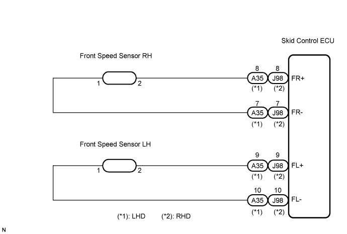
WIRING DIAGRAM
INSPECTION PROCEDURE
CHECK HARNESS AND CONNECTOR (MOMENTARY INTERRUPTION)
READ VALUE OF INTELLIGENT TESTER (FRONT SPEED SENSOR)
PERFORM TEST MODE (SIGNAL CHECK)
RECONFIRM DTC
CHECK FRONT SPEED SENSOR INSTALLATION
CHECK HARNESS AND CONNECTOR (SKID CONTROL SENSOR WIRE)
CHECK HARNESS AND CONNECTOR (SKID CONTROL ECU - FRONT SPEED SENSOR)
INSPECT SKID CONTROL ECU (SENSOR INPUT)
RECONFIRM DTC
REPLACE FRONT SPEED SENSOR
RECONFIRM DTC
REPAIR OR REPLACE HARNESS OR CONNECTOR (SKID CONTROL ECU - FRONT SPEED SENSOR)
RECONFIRM DTC
DTC C0200/31 Front Speed Sensor RH Circuit |
DTC C0205/32 Front Speed Sensor LH Circuit |
DTC C1271/71 Low Output Signal of Front Speed Sensor RH (Test Mode DTC) |
DTC C1272/72 Low Output Signal of Front Speed Sensor LH (Test Mode DTC) |
DESCRIPTION
The speed sensor detects wheel speed and sends the appropriate signals to the skid control ECU. These signals are used for the ABS control system. This speed sensor contains a sensor IC, which consists of 2 MREs (Magnetic Resistance Element). The speed sensor rotor, which consists of 48 sets of N and S poles that are arranged in a circle, is integrated with the inner race of the hub bearing.To detect the rotation direction, the output waves are used to determine the relationship of the pulses that are generated by 2 MREs. Upon receiving this signal, the sensor IC outputs a forward or backward wave to the ECU.DTCs C1271/71 and C1272/72 can be deleted when the speed sensor sends a vehicle speed signal or the Test Mode ends. DTCs C1271/71 and C1272/72 are output only in the Test Mode.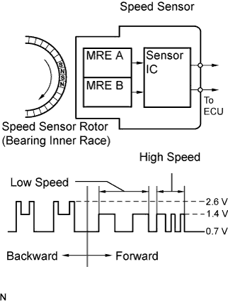
DTC No.
| DTC Detection Condition
| Trouble Area
|
C0200/31
C0205/32
| When any of the following is detected:
- At a vehicle speed of 6 mph (10 km/h) or more, an open or short in the sensor signal circuit continues for 1 second or more.
- Momentary interruption of the sensor signal from the abnormal wheel occurs 255 times or more.
- An open in the speed sensor signal circuit continues for 0.5 seconds or more.
- When the vehicle is driven in reverse at the speed of 1.8 mph (3 km/h) or more and 3 of the wheel sensors detect the reverse signal, the other sensor detects a high frequency pulse 75 times while the engine switch is on (IG).
- At a vehicle speed of 6 mph (10 km/h) or more, the vehicle speed sensor output drops by 50 % for 5 seconds.
- At a vehicle speed of 6 mph (10 km/h) or more, the direction of wheel rotation changes 7 times in 0.006 seconds while the engine switch is on (IG).
- At a vehicle speed of 18 mph (30 km/h) or more, one wheel direction is different from the other 3 wheels' for 1 second.
- At a vehicle speed of 60 mph (100 km/h), a reverse signal is output for 1 second or more.
- At a vehicle speed of 18 mph (30 km/h) or more, the rotation direction of one of the wheels is not detected normally and the rotation direction of the other 3 wheels is not the same for 1 second.
- With the IG1 terminal voltage 9.5 V or more, the sensor power supply voltage decreases for 0.5 seconds or more.
| - Front speed sensor RH/LH
- Speed sensor circuit
- Speed sensor rotor
- Sensor installation
- Skid control ECU
|
- HINT:
- DTC C0200/31 is for the front speed sensor RH.
- DTC C0205/32 is for the front speed sensor LH.
WIRING DIAGRAM
INSPECTION PROCEDURE
- NOTICE:
- When replacing the skid control ECU, perform zero point calibration and store system information (Click here).
| 1.CHECK HARNESS AND CONNECTOR (MOMENTARY INTERRUPTION) |
Using the intelligent tester, check for any momentary interruption in the wire harness and connector corresponding to a DTC (Click here).
ABS / VSC:Item (Display)
| Measurement Item / Range (Display)
| Normal Condition
|
FR Speed Open
| FR speed sensor open detection / ERROR or NORMAL
| ERROR: Momentary interruption
NORMAL: Normal
|
FL Speed Open
| FL speed sensor open detection / ERROR or NORMAL
| ERROR: Momentary interruption
NORMAL: Normal
|
- Result:
Condition
| Proceed to
|
There are no momentary interruptions
| A
|
There are momentary interruptions
| B
|
There is a constant open circuit
| C
|
- HINT:
- Perform the above inspection before removing the sensor and connector.
| 2.READ VALUE OF INTELLIGENT TESTER (FRONT SPEED SENSOR) |
Connect the intelligent tester to the DLC3.
Start the engine.
Select the Data List mode on the intelligent tester.
ABS / VSC:Item (Display)
| Measurement Item / Range (Display)
| Normal Condition
|
FR Wheel Speed
| FR wheel speed sensor reading / min.: 0 mph (0 km/h), max.: 202 mph (326 km/h)
| Actual wheel speed
|
FL Wheel Speed
| FL wheel speed sensor reading /min.: 0 mph (0 km/h), max.: 202 mph (326 km/h)
| Actual wheel speed
|
Check that there is no difference between the speed value output from the speed sensor displayed on the intelligent tester and the speed value displayed on the speedometer when driving the vehicle.
- OK:
- The speed value output from the speed sensor displayed on the intelligent tester is the same as the actual vehicle speed.
ABS / VSC:Item (Display)
| Measurement Item / Range (Display)
| Normal Condition
|
FR Wheel Direction
| FR wheel direction / FORWARD or BACK
| FORWARD: Forward
BACK: Back
|
FL Wheel Direction
| FL wheel direction / FORWARD or BACK
| FORWARD: Forward
BACK: Back
|
Check that the sensor signal conforms to the wheel direction.
- OK:
- The wheel direction is displayed.
| 3.PERFORM TEST MODE (SIGNAL CHECK) |
Perform sensor signal check in Test Mode Procedure (Click here).
- OK:
- All Test Mode DTCs are erased.
Clear the DTC (Click here).
Start the engine.
Drive the vehicle at the speed of 20 mph (32 km/h) or more for at least 60 seconds.
Check if the same DTC is recorded (Click here).
- Result:
Condition
| Proceed to
|
DTCs (C0200/31 and/or C0205/32) are not output
| A
|
DTCs (C0200/31 and/or C0205/32) are output
| B
|
- HINT:
- If troubleshooting has been carried out according to the Problem Symptoms Table, refer back to the table and proceed to the next step (Click here).
| A |
|
|
|
| USE SIMULATION METHOD TO CHECK |
|
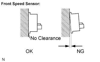
| 5.CHECK FRONT SPEED SENSOR INSTALLATION |
Turn the engine switch off.
Check the speed sensor installation.
- OK:
- There is no clearance between the sensor and the front steering knuckle.
- NOTICE:
- Check the speed sensor signal after replacement (Click here).
| | INSTALL FRONT SPEED SENSOR CORRECTLY |
|
|
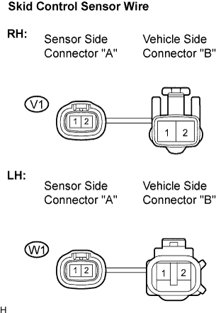
| 6.CHECK HARNESS AND CONNECTOR (SKID CONTROL SENSOR WIRE) |
Disconnect the skid control sensor wire.
Measure the resistance according to the value(s) in the table below.
- Standard resistance:
- RH:
Tester Connection
| Condition
| Specified Condition
|
V1 ("A"-2) - V1 ("B"-1)
| Always
| Below 1 Ω
|
V1 ("A"-2) - V1 ("B"-2)
| Always
| 10 kΩ or higher
|
V1 ("A"-2) - Body ground
| Always
| 10 kΩ or higher
|
V1 ("A"-1) - V1 ("B"-2)
| Always
| Below 1 Ω
|
V1 ("A"-1) - V1 ("B"-1)
| Always
| 10 kΩ or higher
|
V1 ("A"-1) - Body ground
| Always
| 10 kΩ or higher
|
- LH:
Tester Connection
| Condition
| Specified Condition
|
W1 ("A"-2) - W1 ("B"-1)
| Always
| Below 1 Ω
|
W1 ("A"-2) - W1 ("B"-2)
| Always
| 10 kΩ or higher
|
W1 ("A"-2) - Body ground
| Always
| 10 kΩ or higher
|
W1 ("A"-1) - W1 ("B"-2)
| Always
| Below 1 Ω
|
W1 ("A"-1) - W1 ("B"-1)
| Always
| 10 kΩ or higher
|
W1 ("A"-1) - Body ground
| Always
| 10 kΩ or higher
|
- NOTICE:
- Check the speed sensor signal after replacement (Click here).
| | REPLACE SKID CONTROL SENSOR WIRE |
|
|
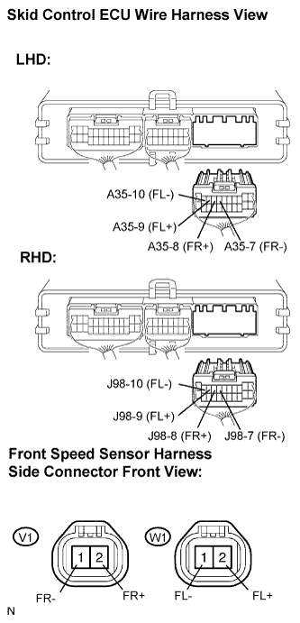
| 7.CHECK HARNESS AND CONNECTOR (SKID CONTROL ECU - FRONT SPEED SENSOR) |
Reconnect the skid control sensor wire.
Disconnect the skid control ECU connector and the front speed sensor connector.
Measure the resistance according to the value(s) in the table below.
- Standard resistance:
- RH (LHD):
Tester Connection
| Condition
| Specified Condition
|
A35-8 (FR+) - V1-2 (FR+)
| Always
| Below 1 Ω
|
A35-8 (FR+) - Body ground
| Always
| 10 kΩ or higher
|
A35-7 (FR-) - V1-1 (FR-)
| Always
| Below 1 Ω
|
A35-7 (FR-) - Body ground
| Always
| 10 kΩ or higher
|
- RH (RHD):
Tester Connection
| Condition
| Specified Condition
|
J98-8 (FR+) - V1-2 (FR+)
| Always
| Below 1 Ω
|
J98-8 (FR+) - Body ground
| Always
| 10 kΩ or higher
|
J98-7 (FR-) - V1-1 (FR-)
| Always
| Below 1 Ω
|
J98-7 (FR-) - Body ground
| Always
| 10 kΩ or higher
|
- LH (LHD):
Tester Connection
| Condition
| Specified Condition
|
A35-9 (FL+) - W1-2 (FL+)
| Always
| Below 1 Ω
|
A35-9 (FL+) - Body ground
| Always
| 10 kΩ or higher
|
A35-10 (FL-) - W1-1 (FL-)
| Always
| Below 1 Ω
|
A35-10 (FL-) - Body ground
| Always
| 10 kΩ or higher
|
- LH (RHD):
Tester Connection
| Condition
| Specified Condition
|
J98-9 (FL+) - W1-2 (FL+)
| Always
| Below 1 Ω
|
J98-9 (FL+) - Body ground
| Always
| 10 kΩ or higher
|
J98-10 (FL-) - W1-1 (FL-)
| Always
| Below 1 Ω
|
J98-10 (FL-) - Body ground
| Always
| 10 kΩ or higher
|
| | REPAIR OR REPLACE HARNESS OR CONNECTOR |
|
|
| 8.INSPECT SKID CONTROL ECU (SENSOR INPUT) |
Reconnect the skid control ECU connector.
Turn the engine switch on (IG).
Measure the voltage according to the value(s) in the table below.
- Standard voltage:
- RH:
Tester Connection
| Condition
| Specified Condition
|
V1-2 (FR+) - Body ground
| Engine switch on (IG)
| 7.5 to 14 V
|
- LH:
Tester Connection
| Condition
| Specified Condition
|
W1-2 (FL+) - Body ground
| Engine switch on (IG)
| 7.5 to 14 V
|
Turn the engine switch off.
Reconnect the front speed sensor connector.
Clear the DTC (Click here).
Start the engine.
Drive the vehicle at the speed of 20 mph (32 km/h) or more for at least 60 seconds.
Check if the same DTC is recorded (Click here).
- Result:
Condition
| Proceed to
|
DTCs (C0200/31 and/or C0205/32) are output
| A
|
DTCs (C0200/31 and/or C0205/32) are not output
| B
|
- HINT:
- If troubleshooting has been carried out according to the Problem Symptoms Table, refer back to the table and proceed to the next step (Click here).
| | USE SIMULATION METHOD TO CHECK |
|
|
| 10.REPLACE FRONT SPEED SENSOR |
Turn the engine switch off.
Replace the front speed sensor (Click here).
- NOTICE:
- Check the speed sensor signal after replacement (Click here).
Clear the DTC (Click here).
Start the engine.
Drive the vehicle at the speed of 20 mph (32 km/h) or more for at least 60 seconds.
Check if the same DTC is recorded (Click here).
- Result:
Condition
| Proceed to
|
DTCs (C0200/31 and/or C0205/32) are output
| A
|
DTCs (C0200/31 and/or C0205/32) are not output
| B
|
- HINT:
- If troubleshooting has been carried out according to the Problem Symptoms Table, refer back to the table and proceed to the next step (Click here).
| 12.REPAIR OR REPLACE HARNESS OR CONNECTOR (SKID CONTROL ECU - FRONT SPEED SENSOR) |
Turn the engine switch off.
Repair or replace the harness or connector.
Check for any momentary interruption between the skid control ECU and front speed sensor (Click here).
Check that there is no momentary interruption.
Clear the DTC (Click here).
Start the engine.
Drive the vehicle at the speed of 20 mph (32 km/h) or more for at least 60 seconds.
Check if the same DTC is recorded (Click here).
- Result:
Condition
| Proceed to
|
DTCs (C0200/31 and/or C0205/32) are not output
| A
|
DTCs (C0200/31 and/or C0205/32) are output
| B
|
- HINT:
- If troubleshooting has been carried out according to the Problem Symptoms Table, refer back to the table and proceed to the next step (Click here).