Brake. Lexus Is250, Is220D. Gse20 Ale20
Brake Control. Lexus Is250, Is220D. Gse20 Ale20
Vehicle Stability Control System (W/ Vdim) -- Terminals Of Ecu |
| CHECK BATTERY VOLTAGE |
Check the battery voltage.
- Standard voltage:
- 10 to 14 V
| SKID CONTROL ECU INSPECTION |
Measure the voltage between each terminal or between each terminal and the body ground.
Connect the intelligent tester to the DLC3, and check the communication condition with the skid control ECU.
Using an oscilloscope, check that the pulse generates between each terminal or between each terminal and the body ground.
- NOTICE:
- Inspection should be performed from the back of the connector with the connector connected to the skid control ECU.
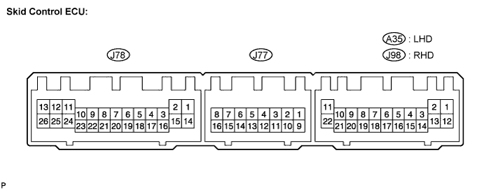
- HINT:
- Inspect the ECU from the wire harness side while the connector is connected.
(*1): LHDSymbols (Terminal No.) Wiring Color Terminal Description Condition Specified Condition SFRR (A35 (*1), J98 (*2)-1) - Body ground GR - Body ground Front decrease solenoid RH output Approx. 1.5 seconds after turning engine switch on (IG) 10 to 14 V SRLR (A35 (*1), J98 (*2)-2) - Body ground R (*1), P (*2) - Body ground Rear decrease solenoid LH output Approx. 1.5 seconds after turning engine switch on (IG) 10 to 14 V MR (A35 (*1), J98 (*2)-3) - Body ground L-B (*1), L (*2) - Body ground Motor relay output Engine switch on (IG) 10 to 14 V FLO (A35 (*1), J98 (*2)-4) - Body ground (*3) R-L (*1), B (*2) - Body ground Front wheel speed signal LH output During the drive Pulse generation
(see waveform 1)FRO (A35 (*1), J98 (*2)-5) - Body ground (*3) G-W (*1), BR (*2) - Body ground Front wheel speed signal RH output During the drive Pulse generation
(see waveform 1)FR- (A35 (*1), J98 (*2)-7) - Body ground G - Body ground Front wheel speed sensor RH input Vehicle speed (forward or back) input Pulse generation
(see waveform 2)FR+ (A35 (*1), J98 (*2)-8) - Body ground L - Body ground Front wheel speed sensor power supply RH output Engine switch on (IG) 10 to 14 V FL+ (A35 (*1), J98 (*2)-9) - Body ground P - Body ground Front wheel speed sensor power supply LH output Engine switch on (IG) 10 to 14 V FL- (A35 (*1), J98 (*2)-10) - Body ground L - Body ground Front wheel speed sensor LH input Vehicle speed (forward or back) input Pulse generation
(see waveform 2)R+ (A35 (*1), J98 (*2)-11) - Body ground G - Body ground Solenoid relay power supply Engine switch on (IG) 10 to 14 V SRRR (A35 (*1), J98 (*2)-12) - Body ground W-L (*1), O (*2) - Body ground Rear decrease solenoid RH output Approx. 1.5 seconds after turning engine switch on (IG) 10 to 14 V SFLR (A35 (*1), J98 (*2)-13) - Body ground W (*1), SB (*2) - Body ground Front decrease solenoid RH output Approx. 1.5 seconds after turning engine switch on (IG) 10 to 14 V SSEL (A35 (*1), J98 (*2)-14) - Body ground Y-B (*1), Y (*2) - Body ground Solenoid characteristic identification input 1 Engine start Low: 0 V (Normal)
Middle: 3.7 to 8.26 V
High: 7.8 to 14 VSEL2 (A35 (*1), J98 (*2)-16) - Body ground B-L (*1), B (*2) - Body ground Solenoid characteristic identification input 2 Engine start Low: 0 V (Normal)
Middle: 3.7 to 8.26 V
High: 7.8 to 14 VFSW+ (A35 (*1), J98 (*2)-18) - Body ground G-B (*1), LG (*2) - Body ground Brake pedal load sensing switch input Stop light switch ON → OFF (Brake pedal depressed → released) Approx. 1 kΩ →
Approx. 213 ΩGND3 (A35 (*1), J98 (*2)-22) - Body ground W-B - Body ground Skid control ECU ground 3 Always Below 1 Ω IG1 (J77-1) - Body ground B - Body ground IG1 power supply Engine switch on (IG) 10 to 14 V RL- (J77-3) - Body ground B - Body ground Rear wheel speed sensor LH input Vehicle speed (forward or back) input Pulse generation
(see waveform 2)RL+ (J77-4) - Body ground LG - Body ground Rear wheel speed sensor power supply LH output Engine switch on (IG) 10 to 14 V RR+ (J77-5) - Body ground B - Body ground Rear wheel speed sensor power supply RH output Engine switch on (IG) 10 to 14 V RR- (J77-6) - Body ground G - Body ground Rear wheel speed sensor RH input Vehicle speed (forward or back) input Pulse generation
(see waveform 2)CSW (J77-7) - Body ground P - Body ground Traction OFF switch input Traction OFF switch ON → OFF Below 1 Ω →
10 kΩ or higherCANH (J77-8) - Body ground R - Body ground CAN communication line H Engine switch off 54 to 67 Ω SP1 (J77-9) - Body ground V - Body ground Speed signal output for combination meter During the drive Pulse generation
(see waveform 3)STP (J77-10) - Body ground R - Body ground Stop light switch input Stop light switch ON → OFF (Brake pedal depressed → released) 10 to 14 V →
Below 1.5 VBZ (J77-11) - Body ground L - Body ground Skid control buzzer output Engine switch on (IG), buzzer sounds → does not sound Below 1 V →
10 to 14 VD/G (J77-12) - Body ground R - Body ground Diagnosis tester communication line Engine switch on (IG) 10 to 14 V TS (J77-13) - Body ground SB - Body ground Sensor check activation input Engine switch on (IG), terminals TS and CG of DLC3 connect → disconnect Below 1.5 V →
10 to 14 VPKB (J77-14) - Body ground R-B - Body ground Parking brake switch input Engine switch on (IG), parking brake switch ON → OFF Below 1 Ω →
10 kΩ or higherWFSE (J77-15) - Body ground GR - Body ground ECU program rewrite input - - CANL (J77-16) - Body ground W - Body ground CAN communication line L Engine switch off 54 to 67 Ω MRF (J78-1) - Body ground L-B - Body ground Fail safe motor relay output Approx. 1.5 seconds after turning engine switch on (IG) Below 1 V SR (J78-2) - Body ground V - Body ground Solenoid relay output Approx. 1.5 seconds after turning engine switch on (IG) Below 1 V PMC (J78-4) - Body ground R - Body ground Master cylinder pressure sensor input Engine switch on (IG), brake pedal released 0.3 to 0.8 V E2 (J78-6) - Body ground W - Body ground Master cylinder pressure sensor ground Always Below 1 Ω RRA+ (J78-7) - Body ground L - Body ground Rear holding solenoid (+) RH output Approx. 1.5 seconds after turning engine switch on (IG) 10 to 14 V FLA- (J78-8) - Body ground W - Body ground Front holding solenoid (-) LH output Approx. 1.5 seconds after turning engine switch on (IG) 10 to 14 V RLA+ (J78-9) - Body ground G - Body ground Rear holding solenoid (+) LH output Approx. 1.5 seconds after turning engine switch on (IG) 10 to 14 V FRA- (J78-10) - Body ground GR - Body ground Front holding solenoid (-) RH output Approx. 1.5 seconds after turning engine switch on (IG) 10 to 14 V SM2+ (J78-11) - Body ground B - Body ground Master cut linear solenoid 2 (+) output Approx. 1.5 seconds after turning engine switch on (IG) Below 1 V SM1- (J78-12) - Body ground R - Body ground Master cut linear solenoid 1 (-) output Approx. 1.5 seconds after turning engine switch on (IG) Below 1 V AST (J78-13) - Body ground Y - Body ground Linear solenoid power supply Approx. 1.5 seconds after turning engine switch on (IG) 10 to 14 V GND2 (J78-14) - Body ground W-B - Body ground Skid control ECU ground 2 Always Below 1 Ω MT (J78-15) - Body ground GR - Body ground Motor relay test input Approx. 1.5 seconds after turning engine switch on (IG) Below 1 V VCM (J78-18) - Body ground B - Body ground Master cylinder pressure sensor power supply output Engine switch on (IG) 4.5 to 5.5 V FSS (J78-19) - Body ground - Master cylinder pressure sensor shielded ground Always Below 1 Ω RRA- (J78-20) - Body ground O - Body ground Rear holding solenoid (-) RH output Approx. 1.5 seconds after turning engine switch on (IG) 10 to 14 V FLA+ (J78-21) - Body ground V - Body ground Front holding solenoid (+) LH output Approx. 1.5 seconds after turning engine switch on (IG) 10 to 14 V RLA- (J78-22) - Body ground P - Body ground Rear holding solenoid (-) LH output Approx. 1.5 seconds after turning engine switch on (IG) 10 to 14 V FRA+ (J78-23) - Body ground LG - Body ground Front holding solenoid (+) RH output Approx. 1.5 seconds after turning engine switch on (IG 10 to 14 V SM2- (J78-24) - Body ground BR - Body ground Master cut linear solenoid 2 (-) output Approx. 1.5 seconds after turning engine switch on (IG) Below 1 V SM1+ (J78-25) - Body ground SB - Body ground Master cut linear solenoid 1 (+) output Approx. 1.5 seconds after turning engine switch on (IG) Below 1 V GND1 (J78-26) - Body ground W-B - Body ground Skid control ECU ground 1 Always Below 1 Ω
(*2): RHD
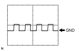
(*3): AFSWaveform 1 (Reference): Using an oscilloscope:
Item Condition Tool setting 5 V/DIV., 5 ms./DIV. Vehicle condition While driving at approximately 12 mph (20 km/h) - HINT:
- As the vehicle speed (tire rotating speed) becomes faster, the cycle becomes shorter.
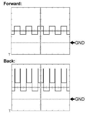
Waveform 2 (Reference): Using an oscilloscope:
Item Condition Tool setting 0.5 V/DIV., 2 ms./DIV. Vehicle condition Forward or back - HINT:
- As the vehicle speed (tire rotating speed) becomes faster, the cycle becomes shorter.
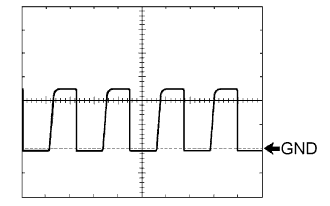
Waveform 3 (Reference): Using an oscilloscope:
Item Condition Tool setting 5 V/DIV., 50 ms./DIV. Vehicle condition While driving at approximately 12 mph (20 km/h) - HINT:
- As the vehicle speed (tire rotating speed) becomes faster, the cycle becomes shorter.
 |
 |
 |