DESCRIPTION
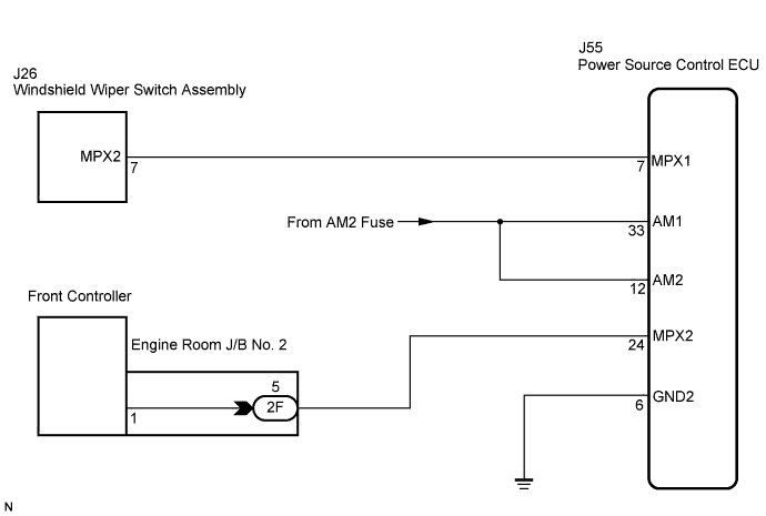
WIRING DIAGRAM
INSPECTION PROCEDURE
INSPECT FUSE (AM2)
CHECK WIRE HARNESS (POWER SOURCE CONTROL ECU - BATTERY AND BODY GROUND)
CHECK RESISTANCE OF COMMUNICATION LINE
DESCRIPTION
- HINT:
- This DTC is only output on vehicles equipped with an entry and start system.
- This DTC is detected when communication between the power source control ECU and gateway ECU stops for more than 10 seconds.
DTC No.
| DTC Detection Condition
| Trouble Area
|
B1210
| Power source control ECU communication stops
| - Power source control ECU
- Wire harness
|
WIRING DIAGRAM
INSPECTION PROCEDURE
Remove the AM2 fuse from the main body ECU (cowl side J/B RH).
Measure the resistance of the fuse.
- Standard resistance:
- Below 1 Ω
| 2.CHECK WIRE HARNESS (POWER SOURCE CONTROL ECU - BATTERY AND BODY GROUND) |
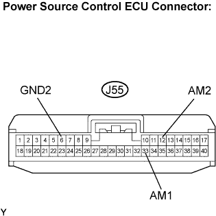
Disconnect the J55 ECU connector.
Measure the resistance and voltage of the wire harness side connector.
- Standard voltage:
Tester Connection
| Condition
| Specified Condition
|
J55-33 (AM1) - Body ground
| Always
| 10 to 14 V
|
J55-12 (AM2) - Body ground
| Always
| 10 to 14 V
|
- Standard resistance:
Tester Connection
| Specified Condition
|
J55-6 (GND2) - Body ground
| Below 1 Ω
|
| | REPAIR OR REPLACE HARNESS OR CONNECTOR |
|
|
| 3.CHECK RESISTANCE OF COMMUNICATION LINE |
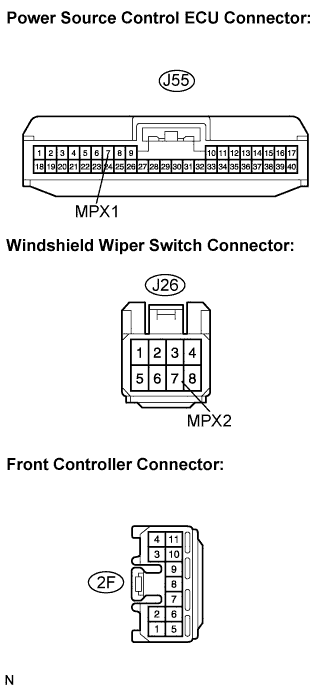
Disconnect the J55, J26 and 2F ECU connectors.
Measure the resistance between the specified terminals on the wire harness side connectors.
- Standard resistance:
Tester Connection
| Specified Condition
|
MPX1 (J55-7) - MPX2 (J26-7)
| Below 1 Ω
|
MPX2 (J55-24) - 2F-5
| Below 1 Ω
|
- Result:
Result
| Proceed to
|
Both are OK
| A
|
One is OK
| B
|
Both are NG
| C
|
| | REPLACE POWER SOURCE CONTROL ECU AND REPAIR OR REPLACE HARNESS OR CONNECTOR |
|
|
| | REPAIR OR REPLACE HARNESS OR CONNECTOR |
|
|
| A |
|
|
|
| REPLACE POWER SOURCE CONTROL ECU |
|