Dtc B1213 Tilt And Telescopic Ecu Communication Stop
DESCRIPTION
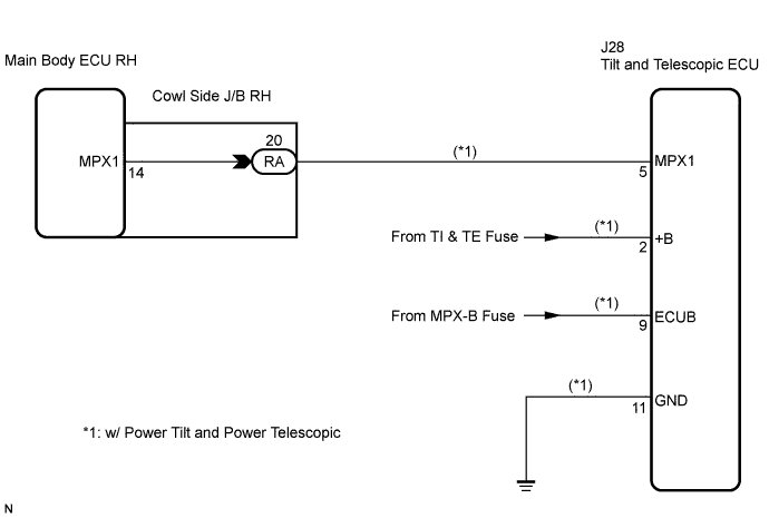
WIRING DIAGRAM
INSPECTION PROCEDURE
INSPECT FUSE (TI & TE, MPX-B)
CHECK WIRE HARNESS (TILT AND TELESCOPIC ECU - BATTERY AND BODY GROUND)
CHECK RESISTANCE OF COMMUNICATION LINE
DTC B1213 Tilt and Telescopic ECU Communication Stop |
DESCRIPTION
- This DTC is detected when communication between the tilt and telescopic ECU and the gateway ECU stops for more than 10 seconds.
DTC No.
| DTC Detection Condition
| Trouble Area
|
B1213
| Tilt and telescopic ECU communication stops
| - Tilt and telescopic ECU
- Wire harness
|
WIRING DIAGRAM
INSPECTION PROCEDURE
- HINT:
- When "+B of GND short malfunction of communication bus" DTCs (B1214 and B1215) are detected at the same time as "communication stop" DTC B1213, repair the "+B or GND short malfunction of communication bus" DTCs first.
| 1.INSPECT FUSE (TI & TE, MPX-B) |
Remove the TI & TE fuse from the main body ECU RH (cowl side J/B RH).
Remove the MPX-B fuse from the engine room J/B No. 1.
Measure the resistance of the fuses.
- Standard resistance:
- Below 1 Ω
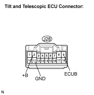
| 2.CHECK WIRE HARNESS (TILT AND TELESCOPIC ECU - BATTERY AND BODY GROUND) |
Disconnect the J28 ECU connector.
Measure the resistance and voltage of the wire harness side connector.
- Standard voltage:
Tester Connection
| Condition
| Specified Condition
|
+B (J28-2) - Body ground
| Always
| 10 to 14 V
|
ECUB (J28-9) - Body ground
| Always
| 10 to 14 V
|
- Standard resistance:
Tester Connection
| Specified Condition
|
GND (J28-11) - Body ground
| Below 1 Ω
|
| | REPAIR OR REPLACE HARNESS OR CONNECTOR |
|
|
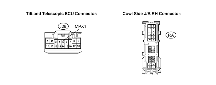
| 3.CHECK RESISTANCE OF COMMUNICATION LINE |
Disconnect the J28 and RA ECU connectors.
Measure the resistance between the specified terminals on the wire harness side connectors.
- Standard resistance:
Tester Connection
| Specified Condition
|
MPX1 (J28-5) - RA-20
| Below 1 Ω
|
MPX1 (J28-5) - Body ground
| 10 kΩ or higher
|
| | REPAIR OR REPLACE HARNESS OR CONNECTOR |
|
|
| OK |
|
|
|
| REPLACE TILT AND TELESCOPIC ECU |
|