2Ad-Fhv Can Communication System (For Rhd) Gateway Ecu Communication Stop Mode
DESCRIPTION
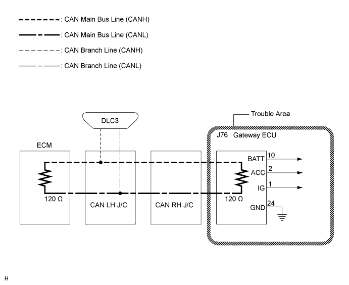
WIRING DIAGRAM
INSPECTION PROCEDURE
CHECK WIRE HARNESS (BATT, ACC, IG, GND)
2AD-FHV CAN COMMUNICATION SYSTEM (for RHD) - Gateway ECU Communication Stop Mode |
DESCRIPTION
Detection Item
| Symptom
| Trouble Area
|
Gateway ECU Communication Stop Mode
| - "Body/Gateway" is not displayed on the "Communication Bus Check" screen of the intelligent tester
- Applies to "Gateway ECU Communication Stop Mode" in the "DTC COMBINATION TABLE"
| - Power source circuit of the gateway ECU
- Gateway ECU
|
- HINT:
- "Body/Gateway" refers to the circuit that includes the gateway ECU.
WIRING DIAGRAM
INSPECTION PROCEDURE
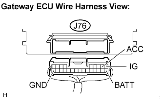
| 1.CHECK WIRE HARNESS (BATT, ACC, IG, GND) |
Turn the engine switch off.
Disconnect the gateway ECU connector (J76).
Measure the resistance according to the value(s) in the table below.
- Standard resistance:
Tester Connection
| Condition
| Specified Value
|
J76-24 (GND) - Body ground
| Always
| Below 1 Ω
|
Measure the voltage according to the value(s) in the table below.
- Standard voltage:
Tester Connection
| Condition
| Specified Value
|
J76-10 (BATT) - Body ground
| Always
| 10 to 14 V
|
J76-2 (ACC) - Body ground
| Engine switch on (IG)
| 10 to 14 V
|
J76-1 (IG) - Body ground
| Engine switch on (IG)
| 10 to 14 V
|
| | REPAIR OR REPLACE HARNESS OR CONNECTOR |
|
|