Can Communication System (For Lhd) Television Camera Ecu Communication Stop Mode
DESCRIPTION
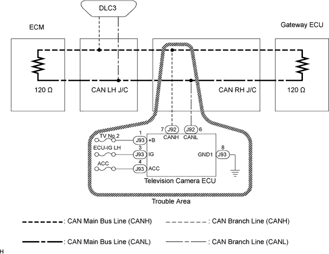
WIRING DIAGRAM
INSPECTION PROCEDURE
CHECK CAN BUS LINE FOR OPEN (TELEVISION CAMERA ECU BRANCH LINE)
CHECK WIRE HARNESS (+B, IG, ACC, GND1)
CAN COMMUNICATION SYSTEM (for LHD) - Television Camera ECU Communication Stop Mode |
DESCRIPTION
Detection Item
| Symptom
| Trouble Area
|
Television Camera ECU Communication Stop Mode
| - "Parking Assist Monitor" is not displayed on the "Communication Bus Check" screen of the intelligent tester
- Applies to "Television Camera ECU Communication Stop Mode" in the "DTC COMBINATION TABLE"
| - Power source circuit of the television camera ECU
- Television camera ECU branch line or connector
- Television camera ECU
|
- HINT:
- "Parking Assist Monitor" refers to the circuit that includes the television camera ECU.
WIRING DIAGRAM
INSPECTION PROCEDURE
| 1.CHECK CAN BUS LINE FOR OPEN (TELEVISION CAMERA ECU BRANCH LINE) |
Turn the engine switch off.
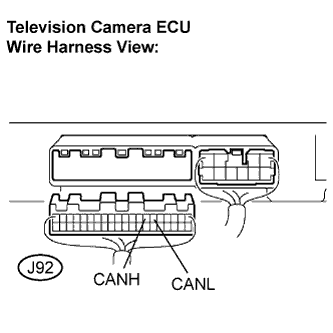
Disconnect the television camera ECU connector (J92).
Measure the resistance according to the value(s) in the table below.
- Standard resistance:
Tester Connection
| Condition
| Specified Value
|
J92-7 (CANH) - J92-6 (CANL)
| Engine switch off
| 54 to 69 Ω
|
| | REPAIR TELEVISION CAMERA ECU BRANCH LINE OR CONNECTOR (CANH, CANL) |
|
|
| 2.CHECK WIRE HARNESS (+B, IG, ACC, GND1) |
Reconnect the television camera ECU connector (J92).
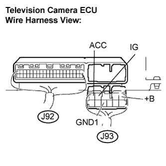
Disconnect the television camera ECU connector (J93).
Measure the resistance according to the value(s) in the table below.
- Standard resistance:
Tester Connection
| Condition
| Specified Value
|
J93-8 (GND1) - Body ground
| Always
| Below 1 Ω
|
Measure the voltage according to the value(s) in the table below.
- Standard voltage:
Tester Connection
| Condition
| Specified Value
|
J93-1 (+B) - Body ground
| Always
| 10 to 14 V
|
J93-3 (IG) - Body ground
| Engine switch on (IG)
| 10 to 14 V
|
J93-4 (ACC) - Body ground
| Engine switch on (ACC)
| 10 to 14 V
|
| | REPAIR OR REPLACE HARNESS OR CONNECTOR |
|
|
| OK |
|
|
|
| REPLACE TELEVISION CAMERA ECU |
|