2Ad-Fhv Can Communication System (For Rhd) -- Diagnosis System |
| BUS CHECK (COMMUNICATION MALFUNCTION DTC) |
- HINT:
- Only CAN communication system DTCs for each ECU can be displayed on the intelligent tester.
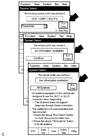
Select "Bus Check" from the "System Select" screen on the intelligent tester.
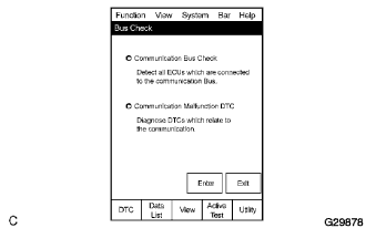
Select "Communication Malfunction DTC" from the "Bus Check" screen, and then select "Enter".
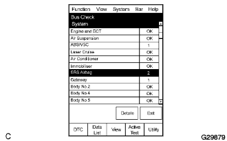
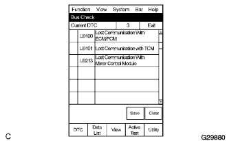
Select the system of the DTC to be checked and select "Details".
CAN communication system DTC(s) is/are displayed.
 |
 |
 |
 |
| BUS CHECK (COMMUNICATION BUS CHECK) |
- HINT:
- The ECUs and sensors that are properly connected to the CAN communication system can be displayed using the intelligent tester.
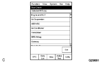
Select "Communication Bus Check" from the "Bus Check" screen.
The screen displays the ECUs and sensors that are properly connected to the CAN communication system.
- HINT:
- If ECUs or sensors that should be properly connected are not displayed, there is a communication stop in the system. (Click here)
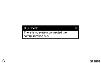
"There is no system connected to the communication bus" is displayed if there are no ECUs or sensors connected to the CAN bus.
|
 |
 |
| CHECK FOR INSTALLED SYSTEMS (ECUS AND SENSORS) THAT ADOPT CAN COMMUNICATION |
Systems (ECUs, sensors) that adopt CAN communication vary depending on the vehicle's optional equipment. Check which systems (ECUs, sensors) are installed on the vehicle.
ECU/Sensor name Check method Skid control ECU (with VDIM) Vehicle stability control system Skid control ECU (without VDIM) Vehicle stability control system Steering angle sensor Installed on all vehicles Yaw rate sensor Installed on all vehicles ECM Installed on all vehicles Gateway ECU Installed on all vehicles Power steering ECU Installed on all vehicles Television camera ECU (with rear view monitor system) Parking assist monitor system Center airbag sensor Installed on all vehicles
| DTC TABLE BY ECU |
ECM/Intelligent tester display "Engine"
- HINT:
- DTC communication uses the CAN communication system.
DTC No. Detection Item U0155 Lost Communication with Combination Meter SKID CONTROL ECU/Intelligent tester display "ABS/VSC/TRC"
- HINT:
- DTC communication uses the SIL line.
DTC No. Detection Item U0073 Control Module Communication Bus Off U0100 Lost Communication With ECM/PCM "A" U0123 Lost Communication With Yaw Rate Sensor Module U0124 Lost Communication With Lateral Acceleration Sensor Module U0126 Lost Communication With Steering Angle Sensor Module POWER STEERING ECU/Intelligent tester display "EPS"
- HINT:
- DTC communication uses the CAN communication system.
DTC No. Detection Item U0105 Lost Communication With ECM U0121 Lost Communication With Anti-lock Brake System (ABS) Control Module TELEVISION CAMERA ECU/Intelligent tester display "Parking Assist Monitor"
- HINT:
- The DTC is displayed on the multi-display assembly (not displayed on the intelligent tester).
DTC No. Detection Item 5C-42 Steering Angle Sensor Communication Line Malfunction GATEWAY ECU
- HINT:
- The gateway ECU is connected to the CAN communication system, but CAN communication DTCs are not output.
CENTER AIRBAG SENSOR
- HINT:
- The center airbag sensor is connected to the CAN communication system, but CAN communication DTCs are not output.
| DTC COMBINATION TABLE |
| DTC | Trouble Mode | ||||
| Output from | Output DTC | Skid Control ECU Communication Stop Mode | Steering Angle Sensor Communication Stop Mode | Yaw Rate Sensor Communication Stop Mode | Gateway ECU Communication Stop Mode |
| Skid Control ECU | U0073 | ○ | X | X | X |
| U0100 | □ During driving | X | X | X | |
| U0123 | ○ | X | ○ | X | |
| U0124 | ○ | X | ○ | X | |
| U0126 | ○ | ○ | X | X | |
| ECM | U0155 | X | X | X | ○ |
| Power Steering ECU | U0105 | X | X | X | X |
| U0121 | ○ | X | X | X | |
| Television Camera ECU | 5C-42 | X | ○ | X | X |
| DTC | Trouble Mode | ||||
| Output from | Output DTC | ECM Communication Stop Mode | Power Steering ECU Communication Stop Mode | Television Camera ECU Communication Stop Mode | Center Airbag Sensor Communication Stop Mode |
| Skid Control ECU | U0073 | X | X | X | X |
| U0100 | □ During driving | X | X | X | |
| U0123 | X | X | X | X | |
| U0124 | X | X | X | X | |
| U0126 | X | X | X | X | |
| ECM | U0155 | X | X | X | X |
| Power Steering ECU | U0105 | ○ | ○ | X | X |
| U0121 | X | ○ | X | X | |
| Television Camera ECU | 5C-42 | X | X | ○ | X |
- HINT:
- ○: Set
- X: Not set or may be set according to the malfunction part when one side of the CAN branch lines opens
- □: Set under the condition shown in the table
- Skid Control ECU Communication Stop Mode: Click here
- Steering Angle Sensor Communication Stop Mode: Click here
- Yaw Rate Sensor Communication Stop Mode: Click here
- Gateway ECU Communication Stop Mode: Click here
- ECM Communication Stop Mode: Click here
- Power Steering ECU Communication Stop Mode: Click here
- Television Camera ECU Communication Stop Mode: Click here
- Center Airbag Sensor Communication Stop Mode: Click here