Engine. Lexus Is250, Is220D. Gse20 Ale20
INSPECTION PROCEDURE
CHECK DTC OUTPUT (RELATED TO ENGINE)
CHECK FUEL FILTER ASSEMBLY
CHECK CRANKING
READ VALUE OF INTELLIGENT TESTER
CHECK INITIAL COMBUSTION
CHECK PRE-HEATING SYSTEM (GLOW INDICATOR LIGHTING TIME AND AFTER GLOW TIME)
READ VALUE OF INTELLIGENT TESTER (FUEL PRESSURE)
CHECK AIR INTAKE SYSTEM AND EXHAUST SYSTEM
READ VALUE OF INTELLIGENT TESTER (FUEL PRESSURE AND INJECTION VOLUME)
CHECK CYLINDER COMPRESSION PRESSURE
CHECK HARNESS AND CONNECTOR (INJECTOR - EDU)
PERFORM ACTIVE TEST BY INTELLIGENT TESTER (CONTROL CYLINDER FUEL CUT)
CHECK FUEL SYSTEM
READ VALUE OF INTELLIGENT TESTER (ENGINE COOLANT TEMPERATURE)
CHECK IDLE SPEED
CHECK HARNESS AND CONNECTOR (STARTER RELAY - ECM)
READ VALUE OF INTELLIGENT TESTER
INSPECT ENGINE COOLANT TEMPERATURE SENSOR
INSPECT CRANKSHAFT POSITION SENSOR
INSPECT COMMON RAIL ASSEMBLY (FUEL PRESSURE SENSOR)
CHECK HARNESS AND CONNECTOR (FUEL PRESSURE SENSOR - ECM)
REPLACE ECM
ECD SYSTEM - Engine Difficult to Start or Stalling |
INSPECTION PROCEDURE
- NOTICE:
- After replacing the ECM, the new ECM needs registration (Click here) and initialization (Click here).
- After replacing a supply pump, the ECM needs initialization (Click here).
- After replacing an injector, the ECM needs registration (Click here).
- HINT:
- Specified values in the following troubleshooting flowchart are for reference only. Variations in the Data List values may occur depending on the measuring conditions or the vehicle's age. Do not assume the vehicle is normal when the Data List outputs standard values. There may be concealed factors of the malfunction.
- If the vehicle runs out of fuel while the engine is operating, there is a chance that the engine may be difficult to restart after the fuel is refilled.
| 1.CHECK DTC OUTPUT (RELATED TO ENGINE) |
Connect the intelligent tester to the DLC3.
Turn the engine switch ON (IG) and turn the intelligent tester ON.
Enter the following menus: Powertrain / Engine / DTC.
Read DTCs.
- Result:
Display (DTC Output)
| Proceed to
|
No output
| A
|
DTCs related to engine
| B
|
| 2.CHECK FUEL FILTER ASSEMBLY |
Check that the fuel filter is not clogged.
- OK:
- Fuel filter is not clogged.
| | REPLACE FUEL FILTER ASSEMBLY |
|
|
Check the engine cranking condition.
Compare the cranking condition with that of a normal engine of the same model, and carefully check if there is any difference between them.
- OK:
- Engine cranking condition is normal.
| | CHECK AND REPLACE CHARGING SYSTEM AND STARTING SYSTEM |
|
|
| 4.READ VALUE OF INTELLIGENT TESTER |
Connect the intelligent tester to the DLC3.
Turn the engine switch ON (IG) and turn the intelligent tester ON.
Enter the following menus: Powertrain / Engine / Data List / Fuel Press.
Read the value.
- Standard:
Item
| Inspection Condition
| Reference Value
|
Fuel Press
| Cranking, and engine coolant temperature 0°C (32°F) or more
| 20 to 55 MPa
|
| 5.CHECK INITIAL COMBUSTION |
Check if initial combustion occurs.
- Result:
Result
| Proceed To
|
No initial combustion with cold engine
| A
|
No initial combustion with hot engine
| B
|
Initial combustion occurs
| C
|
| 6.CHECK PRE-HEATING SYSTEM (GLOW INDICATOR LIGHTING TIME AND AFTER GLOW TIME) |
Check the lighting duration of the glow indicator light (Click here).
- OK:
- Indicator lighting time is normal.
| | REPAIR OR REPLACE PRE-HEATING SYSTEM |
|
|
| 7.READ VALUE OF INTELLIGENT TESTER (FUEL PRESSURE) |
Connect the intelligent tester to the DLC3.
Start the engine and turn the intelligent tester ON.
Enter the following menus: Powertrain / Engine / Data List / Fuel Press.
Check that the internal fuel pressure of the common rail is within the specification below.
- Standard:
Engine Speed
| Fuel Pressure
|
Idling
| Approximately 37 to 43 MPa
|
3,000 rpm (No engine load)
| Approximately 60 to 66 MPa
|
| 8.CHECK AIR INTAKE SYSTEM AND EXHAUST SYSTEM |
Inspect the engine condition (Click here).
| | REPAIR OR REPLACE MALFUNCTIONING PARTS, COMPONENT AND AREA |
|
|
| 9.READ VALUE OF INTELLIGENT TESTER (FUEL PRESSURE AND INJECTION VOLUME) |
Connect the intelligent tester to the DLC3.
Start the engine and turn the intelligent tester ON.
Enter the following menus: Powertrain / Engine / Data List.
Select the following menu items in order and read the values.
- Fuel Press
- Injection Volume
- Standard:
Item
| Engine Speed*
| Reference Value
|
Fuel Press
| Idling
| 37 to 43 MPa
|
Fuel Press
| 2,000 rpm (No engine load)
| 47 to 53 MPa
|
Fuel Press
| 3,000 rpm (No engine load)
| 60 to 66 MPa
|
Injection Volume
| Idling
| 3.9 to 7.0 mm3
|
Injection Volume
| 2,000 rpm (No engine load)
| 5.6 to 9.1 mm3
|
Injection Volume
| 3,000 rpm (No engine load)
| 7.9 to 11.4 mm3
|
- HINT:
- *: If no idling conditions are specified, the shift lever should be in the neutral position, and the A/C switch and all accessory switches should be OFF.
| 10.CHECK CYLINDER COMPRESSION PRESSURE |
Check the cylinder compression pressure (Click here).
- Standard:
- 2,700 kPa (27.5 kgf/cm2, 392 psi)
- Minimum pressure:
- 2,200 kPa (22.4 kgf/cm2, 319 psi)
- Difference between each cylinder:
- 500 kPa (5.1 kgf/cm2, 73 psi)
| | CHECK ENGINE TO DETERMINE CAUSE OF LOW COMPRESSION |
|
|
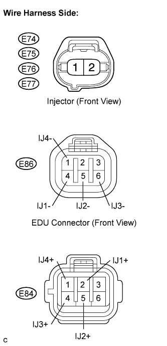
| 11.CHECK HARNESS AND CONNECTOR (INJECTOR - EDU) |
Check the wire harness between the injector and EDU (INJ terminal).
Disconnect the E74, E75, E76 and E77 connectors.
Disconnect the E84 and E86 EDU connectors.
Measure the resistance of the wire harness side connectors.
- Standard resistance:
Tester Connection
| Specified Condition
|
E74-1 - IJ1+ (E84-2)
| Below 1 Ω
|
E75-1 - IJ2+ (E84-5)
| Below 1 Ω
|
E76-1 - IJ3+ (E84-4)
| Below 1 Ω
|
E77-1 - IJ4+ (E84-1)
| Below 1 Ω
|
E74-2 - IJ1- (E86-4)
| Below 1 Ω
|
E75-2 - IJ2- (E86-5)
| Below 1 Ω
|
E76-2 - IJ3- (E86-6)
| Below 1 Ω
|
E77-2 - IJ4- (E86-1)
| Below 1 Ω
|
E74-1 or IJ1+ (E84-2) - Body ground
| 10 kΩ or higher
|
E75-1 or IJ2+ (E84-5) - Body ground
| 10 kΩ or higher
|
E76-1 or IJ3+ (E84-4) - Body ground
| 10 kΩ or higher
|
E77-1 or IJ4+ (E84-1) - Body ground
| 10 kΩ or higher
|
E74-2 or IJ1- (E86-4) - Body ground
| 10 kΩ or higher
|
E75-2 or IJ2- (E86-5) - Body ground
| 10 kΩ or higher
|
E76-2 or IJ3- (E86-6) - Body ground
| 10 kΩ or higher
|
E77-2 or IJ4- (E86-1) - Body ground
| 10 kΩ or higher
|
| | REPAIR OR REPLACE HARNESS OR CONNECTOR |
|
|
| 12.PERFORM ACTIVE TEST BY INTELLIGENT TESTER (CONTROL CYLINDER FUEL CUT) |
Connect the intelligent tester to the DLC3.
Start the engine and turn the intelligent tester ON.
Enter the following menus: Powertrain / Engine / Active Test / Control the Cylinder #1, #2, #3 and #4 Fuel Cut.
Check the engine idle speed while the fuel injection to each cylinder is cut using the intelligent tester.
- Result:
Engine Idling Condition
| Proceed to
|
Becomes unstable
| A
|
Does not change
| B
|
- HINT:
- Replace the injector mounted on the cylinder that causes no significant idle speed change.
| | REPLACE INJECTOR ASSEMBLY |
|
|
Connect the intelligent tester to the DLC3.
Turn the engine switch ON (IG) and turn the tester ON.
Enter the following menus: Powertrain / Engine / Active Test / Activate the Intank Fuel Pump Relay.
Grip the fuel hose to confirm that fuel is being transferred when the fuel pump relay is OK.
- OK:
- Fuel is being transferred.
| | REPLACE SUPPLY PUMP ASSEMBLY |
|
|
| NG |
|
|
|
| GO TO FUEL PUMP CONTROL CIRCUIT |
|
| 14.READ VALUE OF INTELLIGENT TESTER (ENGINE COOLANT TEMPERATURE) |
Connect the intelligent tester to DLC3.
Start the engine and warm it up.
Enter the following menus: Powertrain / Engine / Data List / Coolant Temp.
Read the value.
- Standard:
- 80 to 95°C
Connect the intelligent tester to DLC3.
Turn the engine switch ON (IG) and turn the intelligent tester ON.
Enter the following menus: Powertrain / Engine / Data List / Engine Speed.
Read the value.
- Standard:
- Idling:
- 750 to 1,200 rpm
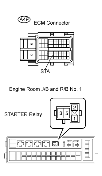
| 16.CHECK HARNESS AND CONNECTOR (STARTER RELAY - ECM) |
Disconnect the A49 ECM connector.
Remove the ST relay from the engine room J/B and R/B No. 1.
Measure the resistance of the wire harness side connectors.
- Standard resistance:
Tester Connection
| Specified Condition
|
R/B ST relay terminal 1 - STA (A49-43)
| Below 1 Ω
|
R/B ST relay terminal 1 or STA (A49-43) - Body ground
| 10 kΩ or higher
|
| | REPAIR OR REPLACE HARNESS OR CONNECTOR |
|
|
| 17.READ VALUE OF INTELLIGENT TESTER |
Connect the intelligent tester to DLC3.
Start the engine and turn the intelligent tester ON.
Enter the following menus: Powertrain / Engine / Data List / Fuel Pressure.
Read the value.
- OK:
- The internal fuel pressure of the common rail is within the specification below.
Engine Speed
| Fuel Pressure
|
Idling
| Approximately 37 to 43 MPa
|
3,000 rpm (No engine load)
| Approximately 60 to 66 MPa
|
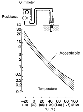
| 18.INSPECT ENGINE COOLANT TEMPERATURE SENSOR |
Remove the sensor.
Measure the resistance of the sensor.
- Standard resistance:
Connection
| Specified Condition
|
20°C (68°F)
| 2.32 to 2.59 kΩ
|
80°C (176°F)
| 0.310 to 0.326 kΩ
|
- NOTICE:
- When checking the sensor in water, keep the terminals dry. After the check, wipe the sensor dry.
- HINT:
- Alternative procedure: Connect an ohmmeter to the installed ECT sensor and read the resistance. Use an infrared thermometer to measure the engine temperature in the immediate vicinity of the sensor. Compare these values against the resistance/ temperature graph. Change the engine temperature (warm up or cool down) and repeat the test.
| | REPLACE ENGINE COOLANT TEMPERATURE SENSOR |
|
|
| OK |
|
|
|
| REPAIR OR REPLACE HARNESS OR CONNECTOR |
|
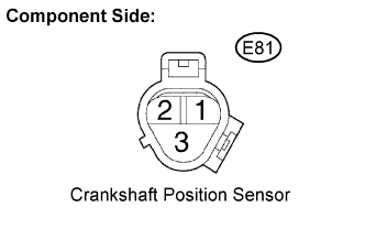
| 19.INSPECT CRANKSHAFT POSITION SENSOR |
Disconnect the E81 sensor connector.
Measure the resistance between terminals 1 and 2.
- Standard resistance:
Tester Connection
| Condition
| Specified Condition
|
1 - 2
| Cold
| 835 to 1,400 Ω
|
1 - 2
| Hot
| 1,060 to 1,645 Ω
|
- NOTICE:
- In the table above, the terms "cold" and "hot" refer to the temperature of the coils in the sensors. "Cold" means approximately -10 to 50°C (14 to 122°F). "Hot" means approximately 50 to 100°C (122 to 212°F).
| | REPLACE CRANKSHAFT POSITION SENSOR |
|
|
| OK |
|
|
|
| REPAIR OR REPLACE HARNESS OR CONNECTOR |
|
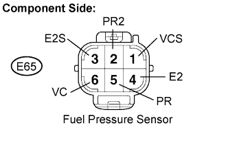
| 20.INSPECT COMMON RAIL ASSEMBLY (FUEL PRESSURE SENSOR) |
Disconnect the E65 fuel sensor connector.
Measure the resistance between each terminal of the fuel pressure sensor connector.
- Standard resistance:
Tester Connection
| Specified Condition
|
PR (E65-5) - E2 (E65-4)
| 16.4 kΩ or less
|
PR2 (E65-2) - E2S (E65-3)
| 16.4 kΩ or less
|
PR (E65-5) - VC (E65-6)
| 3 kΩ or less
|
PR2 (E65-2) - VCS (E65-1)
| 3 kΩ or less
|
Reconnect the fuel pressure sensor connector.
| | REPLACE COMMON RAIL ASSEMBLY |
|
|
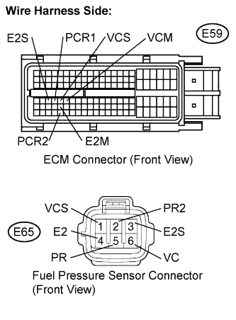
| 21.CHECK HARNESS AND CONNECTOR (FUEL PRESSURE SENSOR - ECM) |
Disconnect the E59 ECM connector.
Disconnect the F65 fuel pressure sensor connector.
Check the resistance between the wire harness side connectors.
- Standard resistance (Check for open):
Tester Connection
| Specified Condition
|
PCR1 (E59-67) - PR (E65-5)
| Below 1 Ω
|
PCR2 (E59-114) - PR2 (E65-2)
| Below 1 Ω
|
VCS (E59-68) - VCS (E65-1)
| Below 1 Ω
|
VCM (E59-69) - VC (E65-6)
| Below 1 Ω
|
E2M (E59-91) - E2 (E65-4)
| Below 1 Ω
|
E2S (E59-66) - E2S (E65-3)
| Below 1 Ω
|
- Standard resistance (Check for short):
Tester Connection
| Specified Condition
|
PCR1 (E59-67) or PR (E65-5) - Body ground
| 10 kΩ or higher
|
PCR2 (E59-114) or PR2 (E65-2) - Body ground
| 10 kΩ or higher
|
VCS (E59-68) or VCS (E65-1) - Body ground
| 10 kΩ or higher
|
VCM (E59-69) or VC (E65-6) - Body ground
| 10 kΩ or higher
|
E2M (E59-91) or E2 (E65-4) - Body ground
| 10 kΩ or higher
|
E2S (E59-66) or E2S (E65-3) - Body ground
| 10 kΩ or higher
|
Reconnect the ECM connector.
Reconnect the fuel pressure sensor connector.
| | REPAIR OR REPLACE HARNESS OR CONNECTOR |
|
|
Replace the ECM.
- NOTICE:
- After replacing the ECM, the new ECM needs registration (Click here) and initialization (Click here)
Check if the engine starts smoothly or if the engine stalls.
- OK:
- The engine starts smoothly and does not stall.
| | REPLACE SUPPLY PUMP ASSEMBLY |
|
|