Dtc B1423/23 Pressure Switch Circuit
DESCRIPTION
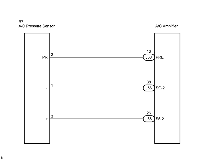
WIRING DIAGRAM
INSPECTION PROCEDURE
CHECK REFRIGERANT
CHECK WIRE HARNESS (PRESSURE SENSOR - A/C AMPLIFIER)
INSPECT PRESSURE SENSOR
DTC B1423/23 Pressure Switch Circuit |
DESCRIPTION
This DTC is output when refrigerant pressure is extremely low (0.19 MPa (2.0 kgf/cm2, 28 psi) or less) or extremely high (3.14 MPa (32.0 kgf/cm2, 455 psi) or more). The pressure sensor, which is installed on the pipe of the high pressure side to detect refrigerant pressure, outputs a refrigerant pressure signal to the A/C amplifier. The A/C amplifier converts this signal to pressure according to the sensor characteristics to control the compressor.- HINT:
- Be sure to check the refrigerant volume first when this DTC is output because this DTC can also be output if there is no refrigerant in the system.
DTC No.
| DTC Detection Condition
| Trouble Area
|
B1423/23
| Open or short in pressure switch circuit
| - Pressure sensor
- Harness and connector between pressure sensor and A/C amplifier
- Refrigerant pipe line
- A/C amplifier
|
WIRING DIAGRAM
INSPECTION PROCEDURE
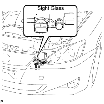
Check the sight glass of the cooler unit refrigerant liquid pipe.
Prepare the vehicle according to the chart below.
Item
| Condition
|
Vehicle Doors
| Fully open
|
Temperature Setting
| MAX COLD
|
Blower Speed
| HI
|
A/C
| ON
|
Compare the sight glass to the following chart.
Item
| Symptom
| Amount of Refrigerant
| Corrective Actions
|
1
| Bubbles visible
| Insufficient*
| - Check for gas leakage and repair if necessary
- Add refrigerant until bubbles disappear
|
2
| No bubbles visible
| Empty, insufficient, or excessive
| Refer to 3 and 4
|
3
| No temperature difference between compressor inlet and outlet
| Empty or nearly empty
| - Check for gas leakage with gas leak detector and repair if necessary
- Evacuate A/C system and recharge with proper amount of refrigerant
|
4
| Considerable temperature difference between compressor inlet and outlet
| Proper or excessive
| Refer to 5 and 6
|
5
| Immediately after air conditioning is turned OFF, refrigerant clears
| Excessive
| - Recover refrigerant
- Evacuate A/C system and recharge with proper amount of refrigerant
|
6
| Immediately after air conditioning is turned OFF, refrigerant foams and then becomes clear
| Proper
| -
|
*: Bubbles in the sight glass with the vehicle interior temperature above 35°C (95°F) can be considered normal if cooling is sufficient.
| 2.CHECK WIRE HARNESS (PRESSURE SENSOR - A/C AMPLIFIER) |
Disconnect the pressure sensor connector.
Disconnect the A/C amplifier connector.
Measure the resistance according to the value(s) in the table below.
- Standard resistance:
Tester Connection
| Condition
| Specified Condition
|
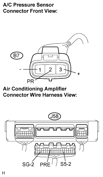
B7-2 (PR) - J58-13 (PRE)
| Always
| Below 1 Ω
|
B7-3 (+) - J58-26 (S5-2)
| Always
| Below 1 Ω
|
B7-1 (-) - J58-38 (SG-2)
| Always
| Below 1 Ω
|
J58-13 (PRE) - Body ground
| Always
| 10 kΩ or higher
|
J58-26 (S5-2) - Body ground
| Always
| 10 kΩ or higher
|
J58-38 (SG-2) - Body ground
| Always
| 10 kΩ or higher
|
| | REPAIR OR REPLACE HARNESS OR CONNECTOR |
|
|
| 3.INSPECT PRESSURE SENSOR |
Install the manifold gauge set (Click here).
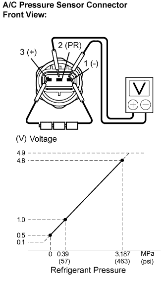
Connect the three 1.5 V dry cell batterie's positive (+) lead to terminal 3 and the negative (-) lead to terminal 1. Then connect the voltmeter's positive (+) lead to terminal 2 and the negative (-) lead to terminal 1. Measure the voltage.
- OK:
- The voltage changes according to refrigerant pressure, as shown in the graph.
- Result:
Result
| Proceed to
|
NG
| A
|
OK (When troubleshooting according to the DTC)
| B
|
OK (When troubleshooting according to the PROBLEM SYMPTOMS TABLE)
| C
|
| | REPLACE AIR CONDITIONING AMPLIFIER |
|
|
| | PROCEED TO NEXT CIRCUIT INSPECTION SHOWN IN PROBLEM SYMPTOMS TABLE |
|
|