Dtc B1244 Light Sensor Circuit Malfunction
Lighting. Lexus Is250, Is220D. Gse20 Ale20
DESCRIPTION
WIRING DIAGRAM
INSPECTION PROCEDURE
CHECK AUTOMATIC LIGHT CONTROL SENSOR (OPERATION)
CHECK HARNESS AND CONNECTOR (MAIN BODY ECU RH - AUTOMATIC LIGHT CONTROL SENSOR)
CHECK AUTOMATIC LIGHT CONTROL SENSOR
DTC B1244 Light Sensor Circuit Malfunction |
DESCRIPTION
This DTC is output when a failure of the automatic light control sensor circuit is detected.DTC No.
| DTC Detection Condition
| Trouble Area
|
B1244
| - Malfunction of automatic light control sensor
- Open or short in automatic light control sensor circuit
| - Automatic light control sensor
- Wire harness or connector
- Main body ECU RH (Cowl side J/B RH)
|
WIRING DIAGRAM
INSPECTION PROCEDURE
| 1.CHECK AUTOMATIC LIGHT CONTROL SENSOR (OPERATION) |
Connect the intelligent tester to the DLC3.
Turn the engine switch on (IG).
Turn the intelligent tester main switch on.
Select the "DATA LIST" on the intelligent tester.
DATA LIST: Body (Main Body ECU RH)Item
| Measurement Item / Display (Range)
| Normal Condition
|
Illumination Rate Info
| Illumination information / 10 to 99.99 ms
| 0.8 to 22 ms
|
The value of the illumination rate should change in the following range when light shines on the automatic light control sensor or when the automatic light control sensor is covered.
- OK:
- 0.8 to 22 ms
- HINT:
- This is the time taken for the automatic light control sensor to generate one cycle of frequency according to the brightness.
| | REPLACE MAIN BODY ECU RH (COWL SIDE J/B RH) |
|
|
| 2.CHECK HARNESS AND CONNECTOR (MAIN BODY ECU RH - AUTOMATIC LIGHT CONTROL SENSOR) |
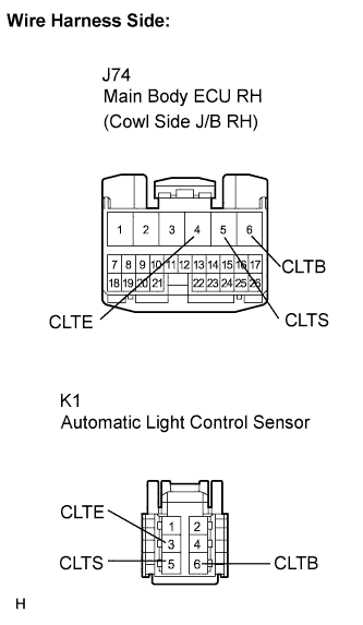
Disconnect the J74 main body ECU RH connector.
Disconnect the K1 automatic light control sensor connector.
Measure the resistance according to the value(s) in the table below.
- Standard resistance:
Tester Connection
| Condition
| Specified Condition
|
J74-6 (CLTB) - K1-6 (CLTB)
| Always
| Below 1 Ω
|
J74-5 (CLTS) - K1-5 (CLTS)
| Always
| Below 1 Ω
|
J74-4 (CLTE) - K1-3 (CLTE)
| Always
| Below 1 Ω
|
J74-6 (CLTB) - Body ground
| Always
| 10 kΩ or higher
|
J74-5 (CLTS) - Body ground
| Always
| 10 kΩ or higher
|
J74-4 (CLTE) - Body ground
| Always
| 10 kΩ or higher
|
Connect the 2 connectors.
| | REPAIR OR REPLACE HARNESS OR CONNECTOR |
|
|
| 3.CHECK AUTOMATIC LIGHT CONTROL SENSOR |
Disconnect the automatic light control sensor.
Measure the resistance according to the value(s) in the table below.
- Standard resistance:
Tester Connection
| Condition
| Specified Condition
|
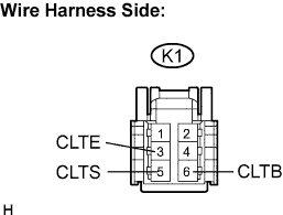
K1-3 (CLTE) - Body ground
| Always
| Below 1 Ω
|
Connect the voltmeter's positive (+) lead to terminal 6 and the negative (-) lead to terminal 3.
Measure the voltage according to the value(s) in the table below.
- Standard voltage:
Tester Connection
| Condition
| Specified Condition
|
K1-3 (CLTE) - K1-6 (CLTB)
| Engine switch on (IG)
| 10 to 14 V
|
Connect the K1 automatic light control sensor connector.
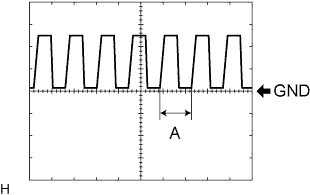
Connect the oscilloscope and check the waveform according to the table below.
- Standard voltage:
Tester Connection
| Condition
| Specified Condition
| Tester Range
|
K1-3 (CLTE) - K1-5 (CLTS)
| Engine switch on (IG), Headlight dimmer switch in AUTO
| Correct waveform is as shown
| 5 V Division, 5 msec/Division
|
If the ambient light becomes brighter, width A becomes narrower.
| | REPLACE AUTOMATIC LIGHT CONTROL SENSOR |
|
|
| OK |
|
|
|
| REPLACE MAIN BODY ECU RH (COWL SIDE J/B RH) |
|