Wiper And Washer System Headlight Cleaner Motor And Relay Circuit
DESCRIPTION
WIRING DIAGRAM
INSPECTION PROCEDURE
INSPECT HEADLIGHT CLEANER MOTOR AND PUMP ASSEMBLY
CHECK HARNESS AND CONNECTOR (HEADLIGHT CLEANER MOTOR CIRCUIT)
WIPER AND WASHER SYSTEM - Headlight Cleaner Motor and Relay Circuit |
DESCRIPTION
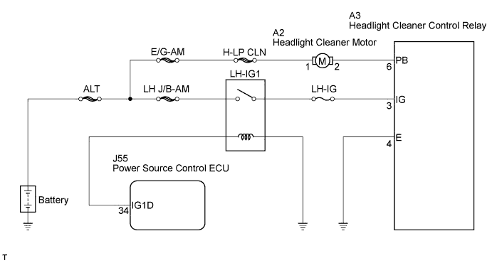
This circuit provides power to the headlight cleaner control relay.The headlight cleaner control relay receives a signal from each switch and sends the signal to the headlight cleaner motor and pump assembly to operate it.
WIRING DIAGRAM
INSPECTION PROCEDURE
| 1.INSPECT HEADLIGHT CLEANER MOTOR AND PUMP ASSEMBLY |
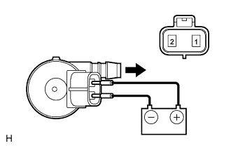
Disconnect the connector from the headlight cleaner motor and pump assembly.
Connect the positive (+) battery lead to terminal 1 of the headlight cleaner motor and pump assembly, and the negative (-) battery lead to terminal 2.
- OK:
- Operation sounds are heard.
| | REPLACE HEADLIGHT CLEANER MOTOR AND PUMP ASSEMBLY |
|
|
| 2.CHECK HARNESS AND CONNECTOR (HEADLIGHT CLEANER MOTOR CIRCUIT) |
Connect the headlight cleaner motor and pump assembly connector.
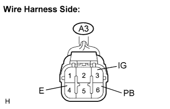
Disconnect the A3 headlight cleaner control relay connector.
Measure the voltage according to the value(s) in the table below.
- Standard voltage:
Tester Connection
| Condition
| Specified Condition
|
A3-3 (IG) - A3-4 (E)
| Engine switch off
| Below 1 V
|
Engine switch on (IG)
| 10 to 14 V
|
A3-6 (PB) - A3-4 (E)
| Always
| 10 to 14 V
|
| | REPAIR OR REPLACE HARNESS OR CONNECTOR (HEADLIGHT CLEANER CONTROL RELAY - BATTERY) |
|
|
| OK |
|
|
|
| PROCEED TO NEXT CIRCUIT INSPECTION SHOWN IN PROBLEM SYMPTOMS TABLE |
|