Rear Drive Shaft Assembly Installation
INSTALL REAR DRIVE SHAFT ASSEMBLY
INSTALL NO. 2 REAR UPPER CONTROL ARM ASSEMBLY
TEMPORARILY TIGHTEN NO. 1 REAR UPPER CONTROL ARM ASSEMBLY
TEMPORARILY TIGHTEN NO. 1 REAR SUSPENSION ARM ASSEMBLY
TEMPORARILY TIGHTEN NO. 2 REAR SUSPENSION ARM ASSEMBLY
INSTALL REAR DISC
INSTALL REAR DISC BRAKE CALIPER ASSEMBLY
INSTALL REAR SPEED SENSOR
INSTALL REAR AXLE SHAFT NUT
INSTALL NO. 3 PARKING BRAKE CABLE ASSEMBLY
INSTALL REAR STABILIZER LINK ASSEMBLY
STABILIZE SUSPENSION
FULLY TIGHTEN NO. 1 REAR UPPER CONTROL ARM ASSEMBLY
FULLY TIGHTEN NO. 1 REAR SUSPENSION ARM ASSEMBLY
FULLY TIGHTEN NO. 2 REAR SUSPENSION ARM ASSEMBLY
INSTALL NO. 2 DIFFERENTIAL SUPPORT PROTECTOR
INSTALL REAR WHEEL
INSPECT AND ADJUST REAR WHEEL ALIGNMENT
CHECK ABS SPEED SENSOR SIGNAL
Rear Drive Shaft Assembly -- Installation |
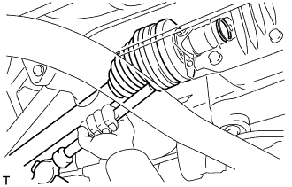
| 1. INSTALL REAR DRIVE SHAFT ASSEMBLY |
Coat the spline of the inboard joint shaft assembly with gear oil.
Set the shaft snap ring with the opening side facing down.
Align the shaft splines and install the drive shaft assembly with a brass bar and hammer.
- NOTICE:
- Be careful not to damage the drive shaft dust cover, boot and oil seal.
- Move the drive shaft assembly while keeping it level.
- HINT:
- It is possible to determine if the inboard joint shaft is properly engaged (the shaft is in contact with the pinion shaft, and the snap ring is engaged in the pinion gear) based on the sound or feeling when the shaft is driven in.
Install the rear drive shaft assembly to the rear axle carrier.
- NOTICE:
- Be careful not to damage the drive shaft boot.
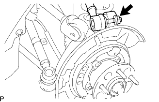
| 2. INSTALL NO. 2 REAR UPPER CONTROL ARM ASSEMBLY |
Install the No. 2 rear upper control arm assembly to the rear axle carrier sub-assembly with a new nut.
- Torque:
- 70 N*m{714 kgf*cm, 52 ft.*lbf}
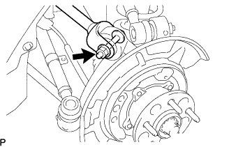
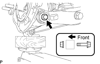
| 3. TEMPORARILY TIGHTEN NO. 1 REAR UPPER CONTROL ARM ASSEMBLY |
Temporarily tighten the No. 1 rear upper control arm assembly to the rear axle carrier sub-assembly with the bolt, washer and nut.
- HINT:
- Install the bolt from the rear side of the vehicle and lightly tighten the bolt.
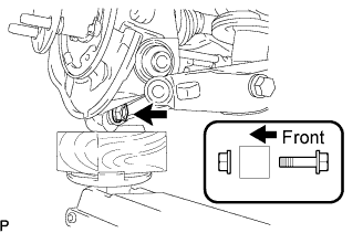
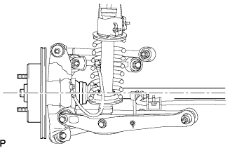
| 4. TEMPORARILY TIGHTEN NO. 1 REAR SUSPENSION ARM ASSEMBLY |
Temporarily tighten the No. 1 rear suspension arm assembly to the rear axle carrier sub-assembly with the bolt and nut.
- HINT:
- Install the bolt from the rear side of the vehicle and lightly tighten the bolt.
| 5. TEMPORARILY TIGHTEN NO. 2 REAR SUSPENSION ARM ASSEMBLY |
Temporarily tighten the No. 2 rear suspension arm assembly to the rear axle carrier sub-assembly with the bolt and nut.
- HINT:
- Install the bolt from the rear side of the vehicle and lightly tighten the bolt.
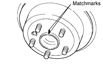
Aligning the matchmarks, install the rear disc.
- HINT:
- When replacing the rear disc with a new one, select the installation position where the rear disc has the minimum runout.
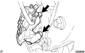
| 7. INSTALL REAR DISC BRAKE CALIPER ASSEMBLY |
Install the rear disc brake caliper assembly and No. 1 caliper plates with the 2 bolts.
- Torque:
- 54 N*m{551 kgf*cm, 40 ft.*lbf}
- NOTICE:
- Do not twist the rear brake hose when installing the rear disc brake caliper.
- Make sure that there are no foreign objects or damage to the threads.
- Do not overtighten the bolts because the hub carrier is made of aluminum and may be damaged.
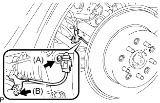
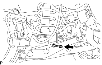
| 8. INSTALL REAR SPEED SENSOR |
Install the speed sensor to the rear axle carrier with the 2 bolts.
- Torque:
- Bolt (A):
- 8.5 N*m{87 kgf*cm, 75 in.*lbf}
- Bolt (B):
- 6.0 N*m{61 kgf*cm, 53 in.*lbf}
- NOTICE:
- Be careful not to damage the speed sensor.
- Prevent foreign matter from adhering to the speed sensor.
- Do not twist the sensor wire when installing the speed sensor.
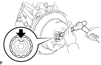
| 9. INSTALL REAR AXLE SHAFT NUT |
Install a new axle shaft nut.
- Torque:
- 290 N*m{2,957 kgf*cm, 214 ft.*lbf}
Using a chisel and a hammer, stake the axle shaft nut.
| 10. INSTALL NO. 3 PARKING BRAKE CABLE ASSEMBLY |
Install the No. 3 parking brake cable assembly with the 2 bolts.
- Torque:
- 19 N*m{194 kgf*cm, 14 ft.*lbf}
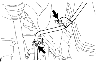
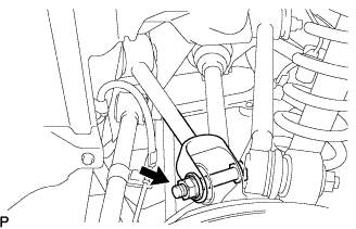
| 11. INSTALL REAR STABILIZER LINK ASSEMBLY |
Install the stabilizer link assembly and the load sensing valve sensor bracket to the No. 2 rear suspension arm assembly with the bolt and nut.
- Torque:
- 27 N*m{275 kgf*cm, 20 ft.*lbf}
Install the rear wheels.
Lower the vehicle to the ground. Bounce the vehicle up and down at the corners to stabilize the rear suspension.
Remove the rear wheels.
Jack up the axle carrier, with a wooden block placed between the jack and axle carrier, to apply a load to the suspension so that the rear drive shaft assembly becomes level.
| 13. FULLY TIGHTEN NO. 1 REAR UPPER CONTROL ARM ASSEMBLY |
Fully tighten the No. 1 rear upper control arm assembly with the nut.
- Torque:
- 161 N*m{1,642 kgf*cm, 119 ft.*lbf}
| 14. FULLY TIGHTEN NO. 1 REAR SUSPENSION ARM ASSEMBLY |
Temporarily tighten the No. 1 rear suspension arm assembly to the rear axle carrier sub-assembly with the bolt and nut.
- HINT:
- Install the bolt from the rear side of the vehicle and lightly tighten the bolt.
| 15. FULLY TIGHTEN NO. 2 REAR SUSPENSION ARM ASSEMBLY |
Fully tighten the No. 2 rear suspension arm assembly with the bolt and nut.
- Torque:
- 161 N*m{1,642 kgf*cm, 119 ft.*lbf}
- NOTICE:
- Turn the bolt while holding the nut.
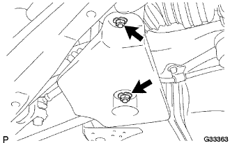
| 16. INSTALL NO. 2 DIFFERENTIAL SUPPORT PROTECTOR |
Install the No. 2 differential support protector to the rear suspension member brace with the 2 nuts.
- Torque:
- 5.4 N*m{55 kgf*cm, 48 in.*lbf}
- Torque:
- 103 N*m{1,050 kgf*cm, 76 ft.*lbf}
| 18. INSPECT AND ADJUST REAR WHEEL ALIGNMENT |
(Click here)
| 19. CHECK ABS SPEED SENSOR SIGNAL |
(Click here)