Rear Propeller Shaft Assembly -- Installation |
| 1. INSTALL PROPELLER SHAFT WITH CENTER BEARING ASSEMBLY |
Remove the SST from the transmission.
- SST
- 09325-40010
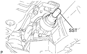 |
Insert the yoke of the intermediate shaft into the transmission.
- HINT:
- Be careful not to damage the oil seal.
Install the 2 center support bearing washers and center support bearing. (for automatic transmission)
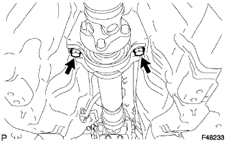 |
Install the 2 center support bearing washers, center support bearing and 2 center support bearing dampers. (for manual transmission)
Temporarily tighten the 2 bolts.
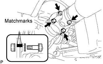
Align the matchmarks on the propeller shaft flange and differential companion flange, and connect the shaft with the 4 bolts, washers and nuts.
- Torque:
- 74 N*m{750 kgf*cm, 54 ft.*lbf}
 |
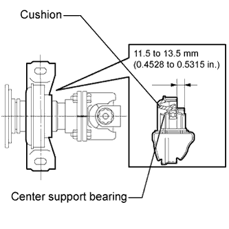
Adjust the dimension between the edge surface of the center support bearing and the edge surface of the cushion to 11.5 to 13.5 mm (0.4528 to 0.5315 in.) as shown in illustration.
 |
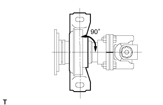
Check that the center line of the bracket is perpendicular to the shaft axial direction.
 |
Tighten the 2 bolts.
- Torque:
- 49 N*m{500 kgf*cm, 36 ft.*lbf}
|
| 2. INSPECT AND ADJUST BOTH NO. 2 AND NO. 3 JOINT ANGLES |
Stabilize the propeller shaft and differential.
Turn the propeller shaft several times by hand to stabilize the center support bearing.
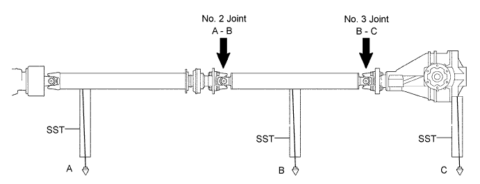
Check both the No. 2 and No. 3 joint angles.
Using SST, measure the installation angle of the intermediate shaft and propeller shaft.
- SST
- 09370-50010
- HINT:
- The SST should be set directly on the bottom of the shaft.
Using SST, measure the installation angle of the differential.
- SST
- 09370-50010
- HINT:
- Measure the installation angle by placing the SST in the positions shown in the illustration.
Calculate the No. 2 joint angle.
- No. 2 joint angle:
- A - B = -1°13' to -0°13'
- A:
- Intermediate shaft installation angle
- B:
- Propeller shaft installation angle
Calculate the No. 3 joint angle.
- No. 3 joint angle:
- B - C = 1°30' to 2°30'
- B:
- Propeller shaft installation angle
- C:
- Differential installation angle
- HINT:
- If the measured angle is not within the specified range, adjust it with the center support bearing washers.
Adjust the No. 2 joint angle .
Select the center support bearing washers for adjustment.
Adjustment washer (for manual transmission) Thickness mm (in) 2 (0.078) 4.5 (0.1772) 6.5 (0.2559) 9.0 (0.3543) 11 (0.4331) Adjustment washer (for automatic transmission) Thickness mm (in) 2 (0.078) 4.5 (0.1772) 6.5 (0.2559) 9.0 (0.3543) 11 (0.4331) 13.5 (0.5315) - NOTICE:
- The 2 washers should be the same thickness.
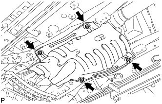
| 3. INSTALL FRONT NO. 1 FLOOR HEAT INSULATOR |
Install the No. 1 heat insulator with the 4 nuts.
- Torque:
- 5.4 N*m{55 kgf*cm, 48 in.*lbf}
 |
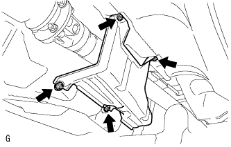
| 4. INSTALL OUTSIDE AIR GUIDE PLATE RH |
Install the air guide plate outside RH with the 4 nuts.
- Torque:
- 5.4 N*m{55 kgf*cm, 48 in.*lbf}
 |
| 5. INSTALL FRONT EXHAUST PIPE ASSEMBLY |
| 6. CHECK FOR EXHAUST GAS LEAKAGE |