Clutch Pedal Installation
Clutch. Lexus Is250, Is220D. Gse20 Ale20
INSTALL CLUTCH MASTER CYLINDER PUSH ROD CLEVIS BUSHING
INSTALL CLUTCH PEDAL PAD
INSTALL CLUTCH PEDAL CUSHION (for LHD)
INSTALL CLUTCH PEDAL CUSHION (for RHD)
INSTALL CLUTCH PEDAL SHAFT COLLAR
INSTALL CLUTCH PEDAL TURNOVER BUSHING
INSTALL CLUTCH PEDAL SUB-ASSEMBLY
INSTALL CLUTCH PEDAL SPRING HOLDER
INSTALL PEDAL WITH HOOK SPRING
INSTALL CLUTCH MASTER CYLINDER PUSH ROD CLEVIS PIN
INSTALL CLUTCH PEDAL SUPPORT SUB-ASSEMBLY (for LHD)
INSTALL CLUTCH PEDAL SUPPORT SUB-ASSEMBLY (for RHD)
CONNECT CLUTCH LINE
CONNECT CLUTCH RESERVOIR TUBE (for LHD)
CONNECT CLUTCH RESERVOIR TUBE (for RHD)
INSTALL WIRE HARNESS (for LHD)
INSTALL WIRE HARNESS (for RHD)
BLEED CLUTCH LINE
CHECK FOR BRAKE FLUID LEAKAGE
INSPECT AND ADJUST CLUTCH PEDAL HEIGHT
INSTALL DRIVER SIDE KNEE AIRBAG ASSEMBLY
INSTALL LOWER INSTRUMENT PANEL FINISH PANEL SUB-ASSEMBLY
INSTALL NO. 1 INSTRUMENT PANEL UNDER COVER SUB-ASSEMBLY
INSTALL SIDE INSTRUMENT PANEL LH
INSTALL FRONT DOOR OPENING TRIM COVER
INSTALL FRONT DOOR SCUFF PLATE (w/o Illumination)
INSTALL FRONT DOOR SCUFF PLATE (w/ Illumination)
CONNECT CABLE TO BATTERY NEGATIVE TERMINAL
CHECK BRAKE FLUID LEVEL IN RESERVOIR
PERFORM INITIALIZATION
INSPECT SRS WARNING LIGHT
Clutch Pedal -- Installation |
- HINT:
- Use the same procedures for the RHD and LHD.
- The procedures listed below are for the LHD.
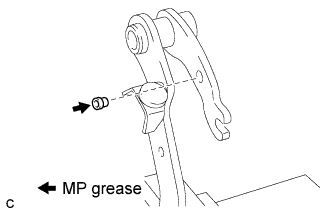
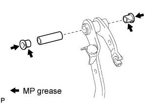
| 1. INSTALL CLUTCH MASTER CYLINDER PUSH ROD CLEVIS BUSHING |
Apply MP grease to the inside of a new clevis bushing.
Install the clevis bushing to the clutch pedal.
- HINT:
- Install the clevis bushing from the left side of the vehicle.
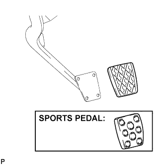
| 2. INSTALL CLUTCH PEDAL PAD |
Install the clutch pedal pad to the clutch pedal.
| 3. INSTALL CLUTCH PEDAL CUSHION (for LHD) |
Using needle-nose pliers, install the 3 clutch pedal cushions to the clutch pedal.
| 4. INSTALL CLUTCH PEDAL CUSHION (for RHD) |
Using needle-nose pliers, install the 4 clutch pedal cushions to the clutch pedal.
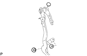
| 5. INSTALL CLUTCH PEDAL SHAFT COLLAR |
Apply MP grease to the inner, outer and end surfaces of 2 new pedal bushings.
Install the clutch pedal shaft collar and 2 pedal bushings to the clutch pedal.
| 6. INSTALL CLUTCH PEDAL TURNOVER BUSHING |
Apply MP grease to the inside of the turnover bushing.
Install the turnover bushing to the clutch pedal.
| 7. INSTALL CLUTCH PEDAL SUB-ASSEMBLY |
Install the clutch pedal to the clutch pedal support with the pedal shaft, washer, and nut.
- Torque:
- 37 N*m{375 kgf*cm, 27 ft.*lbf}
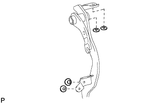
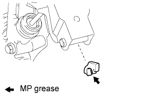
| 8. INSTALL CLUTCH PEDAL SPRING HOLDER |
Apply MP grease to the inside of a new clutch pedal spring holder.
Install the clutch pedal spring holder.
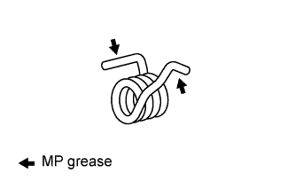
| 9. INSTALL PEDAL WITH HOOK SPRING |
Apply MP grease to the sliding portion of the spring.
Install the hook spring.
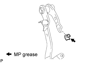
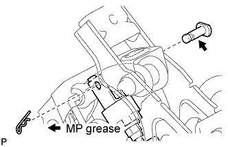
| 10. INSTALL CLUTCH MASTER CYLINDER PUSH ROD CLEVIS PIN |
Apply MP grease to the contact surface of the pin and clevis bushing.
Connect the clevis to the clutch pedal with the pin.
- HINT:
- Install a pin from the left side of the vehicle.
Install the new clip to the pin.
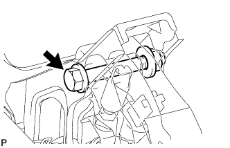
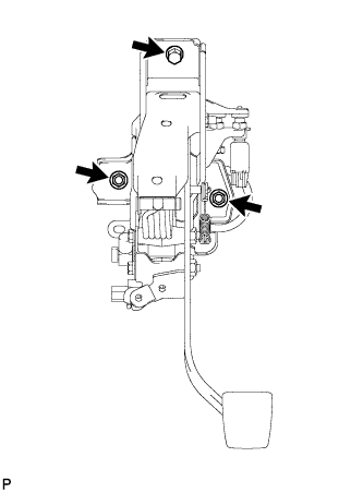
| 11. INSTALL CLUTCH PEDAL SUPPORT SUB-ASSEMBLY (for LHD) |
Install the clutch pedal support with the 2 nuts and bolt.
- Torque:
- 19 N*m{190 kgf*cm, 14 ft.*lbf}
| 12. INSTALL CLUTCH PEDAL SUPPORT SUB-ASSEMBLY (for RHD) |
Install the clutch pedal support with the 2 nuts and bolt.
- Torque:
- 24 N*m{241 kgf*cm, 17 ft.*lbf}
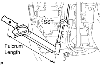
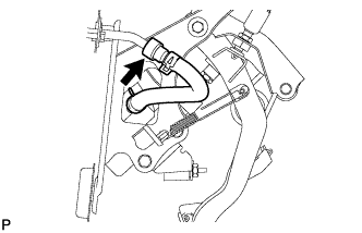
Using SST, connect the clutch line.
- SST
- 09023-00101
- Torque:
- 15 N*m{153 kgf*cm, 11 ft.*lbf}
- HINT:
- Use a torque wrench with a fulcrum length of 300 mm (11.81 in.).
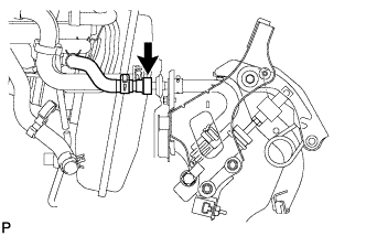
| 14. CONNECT CLUTCH RESERVOIR TUBE (for LHD) |
Connect the clutch reservoir tube.
| 15. CONNECT CLUTCH RESERVOIR TUBE (for RHD) |
Connect the clutch reservoir tube.
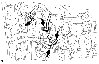
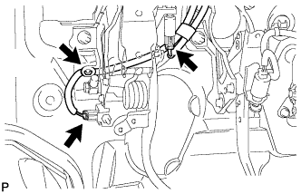
| 16. INSTALL WIRE HARNESS (for LHD) |
Connect the 3 connectors and clamp.
| 17. INSTALL WIRE HARNESS (for RHD) |
Connect the 2 connectors and clamp.
Fill the brake reservoir with the brake fluid and bleed the clutch system (Click here).
- Torque:
- 11 N*m{112 kgf*cm, 8 ft.*lbf}
| 19. CHECK FOR BRAKE FLUID LEAKAGE |
- HINT:
- Check for leakage in the clutch system.
| 20. INSPECT AND ADJUST CLUTCH PEDAL HEIGHT |
(Click here)
| 21. INSTALL DRIVER SIDE KNEE AIRBAG ASSEMBLY |
Connect the connector.
- NOTICE:
- When handling the airbag connector, take care not to damage the airbag wire harness.
Install the driver side knee airbag assembly with the 4 bolts.
- Torque:
- 10 N*m{102 kgf*cm, 7 ft.*lbf}
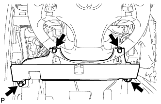
| 22. INSTALL LOWER INSTRUMENT PANEL FINISH PANEL SUB-ASSEMBLY |
Connect the connectors.
Engage the 7 clips and install the lower instrument panel finish panel sub-assembly.
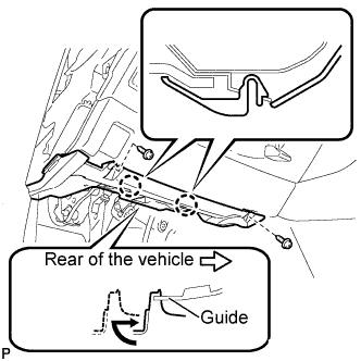
| 23. INSTALL NO. 1 INSTRUMENT PANEL UNDER COVER SUB-ASSEMBLY |
Connect the connectors.
Insert the No. 1 instrument panel under cover sub-assembly into the guide as shown in the illustration.
Engage the 2 claws.
Install the No. 1 instrument panel under cover sub-assembly with the 2 screws <E>.
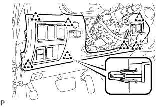
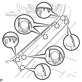
| 24. INSTALL SIDE INSTRUMENT PANEL LH |
Engage the 5 claws and 3 clips, and then install the side instrument panel LH.
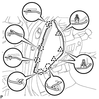
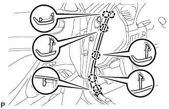
| 25. INSTALL FRONT DOOR OPENING TRIM COVER |
Engage the 6 claws and install the front door opening trim cover LH.
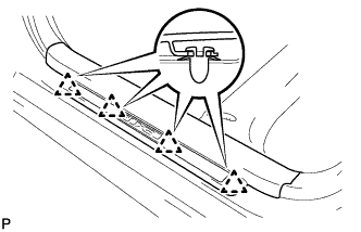
| 26. INSTALL FRONT DOOR SCUFF PLATE (w/o Illumination) |
Engage the 4 clips.
Engage the 7 claws, and install the front door scuff plate LH.
| 27. INSTALL FRONT DOOR SCUFF PLATE (w/ Illumination) |
Connect the connector.
Engage the 4 clips.
Engage the 7 claws, and install the front door scuff plate LH.
| 28. CONNECT CABLE TO BATTERY NEGATIVE TERMINAL |
| 29. CHECK BRAKE FLUID LEVEL IN RESERVOIR |
| 30. PERFORM INITIALIZATION |
Some systems need initialization after reconnecting the negative battery terminal (Click here).
| 31. INSPECT SRS WARNING LIGHT |
(Click here)