Clearance Sonar System No. 1 Clearance Warning Buzzer Circuit
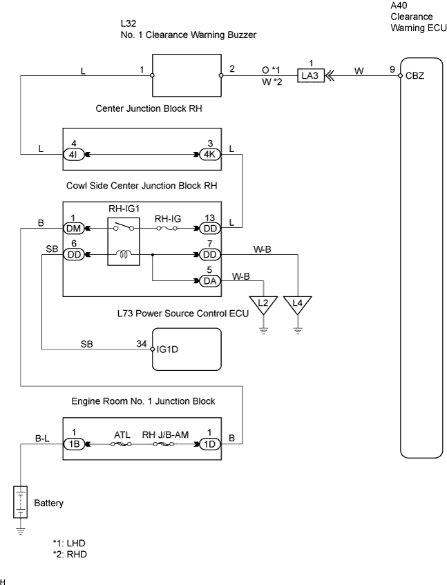
WIRING DIAGRAM
INSPECTION PROCEDURE
PERFORM ACTIVE TEST BY INTELLIGENT TESTER
CHECK WIRE HARNESS (NO. 1 CLEARANCE WARNING BUZZER - CLEARANCE WARNING ECU)
CHECK NO. 1 CLEARANCE WARNING BUZZER (TERMINAL VOLTAGE)
CLEARANCE SONAR SYSTEM - No. 1 Clearance Warning Buzzer Circuit |
WIRING DIAGRAM
INSPECTION PROCEDURE
| 1.PERFORM ACTIVE TEST BY INTELLIGENT TESTER |
Connect the intelligent tester to the DLC3.
Turn the engine switch on (IG).
Turn the intelligent tester main switch ON.
Turn the clearance sonar main switch ON.
Select the Active Test, use the intelligent tester to generate a control command, and then check that the buzzer operates.
Clearance warning ECU:Item
| Vehicle Condition / Test Details
| Diagnostic Note
|
Front Buzzer
| Front buzzer (Clearance warning buzzer) / STOP or OPERATE
| -
|
- OK:
- No. 1 clearance warning buzzer sounds.
| | REPLACE CLEARANCE WARNING ECU |
|
|
| 2.CHECK WIRE HARNESS (NO. 1 CLEARANCE WARNING BUZZER - CLEARANCE WARNING ECU) |
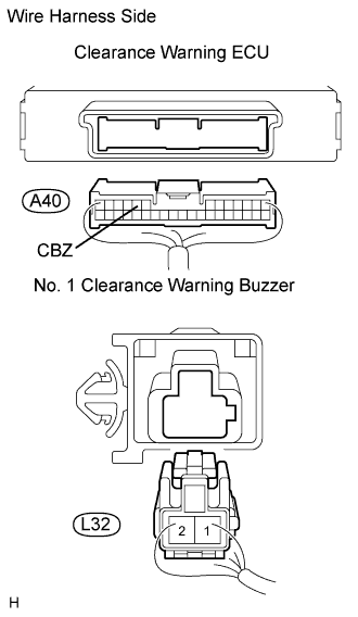
Disconnect the A40 ECU connector.
Disconnect the L32 buzzer connector.
Measure the resistance of the wire harness side connectors.
- Standard resistance:
Tester Connection
| Condition
| Specified Condition
|
A40-9 (CBZ) - L32-2
| Always
| Below 1 Ω
|
A40-9 (CBZ) - Body ground
| Always
| 1 MΩ or higher
|
| | REPAIR OR REPLACE HARNESS AND CONNECTOR |
|
|
| 3.CHECK NO. 1 CLEARANCE WARNING BUZZER (TERMINAL VOLTAGE) |
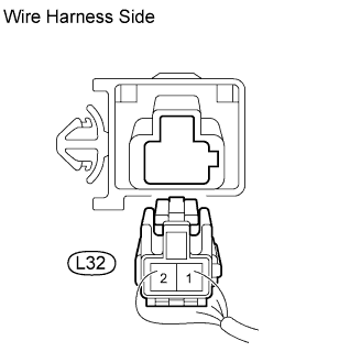
Disconnect the L32 buzzer connector.
Measure the voltage of the wire harness side connector.
- Standard voltage:
Tester Connection
| Condition
| Specified Condition
|
L32-1 - Body ground
| Engine switch on (IG)
| 10 to 14 V
|
| | REPAIR OR REPLACE HARNESS AND CONNECTOR (NO. 1 CLEARANCE WARNING BUZZER - BATTERY) |
|
|
| OK |
|
|
|
| REPLACE NO. 1 CLEARANCE WARNING BUZZER |
|