Brake Booster (W/ Vsc) Removal
Brake. Lexus Gs430, Gs300. Uzs190 Grs190
Brake. Lexus Gs430, Gs300. Uzs190 Grs190
DISCONNECT CABLE FROM NEGATIVE BATTERY TERMINAL
REMOVE COOL AIR INTAKE DUCT SEAL
REMOVE ENGINE ROOM SIDE COVER LH
REMOVE ENGINE ROOM SIDE COVER RH
REMOVE FRONT PILLAR TO FRONT SIDE SEAL SUB-ASSEMBLY LH
REMOVE FRONT PILLAR TO FRONT SIDE SEAL SUB-ASSEMBLY RH
REMOVE FRONT WIPER ARM AND BLADE ASSEMBLY LH
REMOVE FRONT WIPER ARM AND BLADE ASSEMBLY RH
REMOVE FRONT FENDER TO COWL SIDE SEAL LH
REMOVE FRONT FENDER TO COWL SIDE SEAL RH
REMOVE COWL TOP VENTILATOR LOUVER SUB-ASSEMBLY
DRAIN BRAKE FLUID
REMOVE FRONT WHEEL
REMOVE ENGINE ROOM RELAY NO.3 BLOCK
REMOVE BRAKE MASTER WITH PLATE CYLINDER SUB-ASSEMBLY
REMOVE ABS AND TRACTION ACTUATOR ASSEMBLY WITH BRACKET
REMOVE CONSOLE UPPER PANEL GARNISH
REMOVE CONSOLE UPPER PANEL SUB-ASSEMBLY
REMOVE INSTRUMENT PANEL FINISH PANEL END LH (for LHD)
REMOVE INSTRUMENT PANEL FINISH PANEL END RH (for RHD)
REMOVE FRONT DOOR SCUFF PLATE LH (for LHD)
REMOVE FRONT DOOR SCUFF PLATE RH (for RHD)
REMOVE FRONT DOOR OPENING TRIM COVER LH (for LHD)
REMOVE FRONT DOOR OPENING TRIM COVER RH (for RHD)
REMOVE INSTRUMENT SIDE PANEL LH (for LHD)
REMOVE INSTRUMENT SIDE PANEL RH (for RHD)
REMOVE INSTRUMENT PANEL UNDER NO.1 COVER SUB-ASSEMBLY
REMOVE INSTRUMENT PANEL NO.1 SAFETY PAD SUB-ASSEMBLY
REMOVE DRIVER SIDE KNEE AIRBAG ASSEMBLY
REMOVE BRAKE PEDAL RETURN SPRING
SEPARATE BRAKE MASTER CYLINDER PUSH ROD CLEVIS
REMOVE BRAKE BOOSTER ASSEMBLY
REMOVE BRAKE BOOSTER GASKET
REMOVE BRAKE VACUUM CHECK VALVE ASSEMBLY
REMOVE BRAKE MASTER CYLINDER PUSH ROD CLEVIS
Brake Booster (W/ Vsc) -- Removal |
| 1. DISCONNECT CABLE FROM NEGATIVE BATTERY TERMINAL |
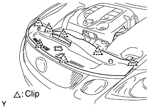
| 2. REMOVE COOL AIR INTAKE DUCT SEAL |
Remove the 7 clips and duct seal.
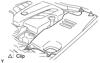
| 3. REMOVE ENGINE ROOM SIDE COVER LH |
Remove the 3 clips and side cover.
| 4. REMOVE ENGINE ROOM SIDE COVER RH |
Remove the nut, 2 clips and side cover.
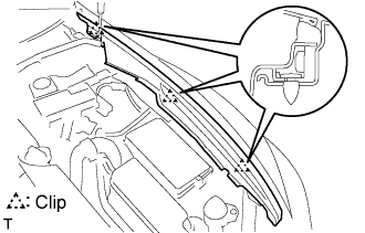
| 5. REMOVE FRONT PILLAR TO FRONT SIDE SEAL SUB-ASSEMBLY LH |
Using a clip remover, detach the 3 clips and remove the side seal.
| 6. REMOVE FRONT PILLAR TO FRONT SIDE SEAL SUB-ASSEMBLY RH |
- HINT:
- Use the same procedures described for the LH side.
| 7. REMOVE FRONT WIPER ARM AND BLADE ASSEMBLY LH |
Remove the nut, wiper arm and blade.
| 8. REMOVE FRONT WIPER ARM AND BLADE ASSEMBLY RH |
Remove the nut, wiper arm and blade.
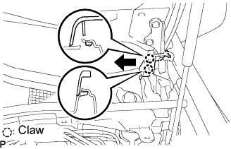
| 9. REMOVE FRONT FENDER TO COWL SIDE SEAL LH |
Pull the cowl side seal in the direction indicated by the arrow in the illustration to detach the 2 claws and remove the cowl side seal.
| 10. REMOVE FRONT FENDER TO COWL SIDE SEAL RH |
- HINT:
- Use the same procedures described for the LH side.
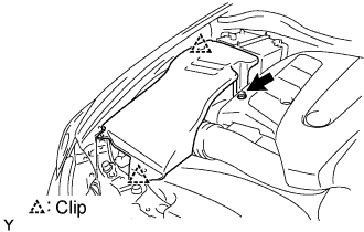
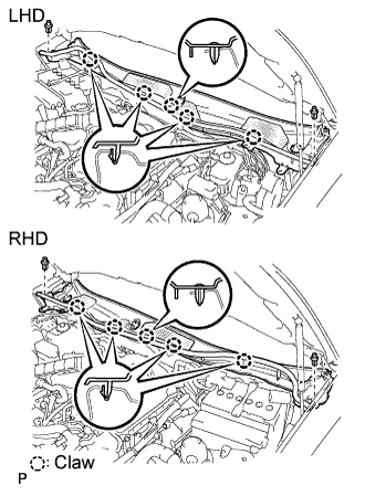
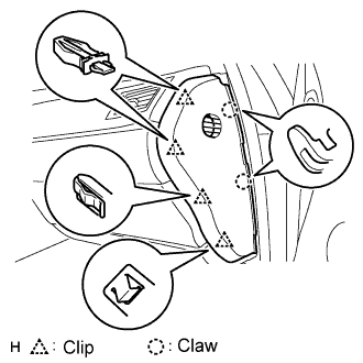
| 11. REMOVE COWL TOP VENTILATOR LOUVER SUB-ASSEMBLY |
Remove the 2 clips and detach the 5 claws.
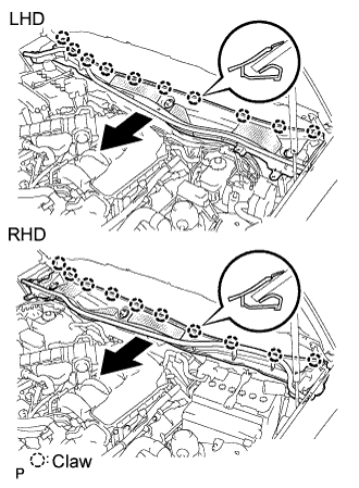
Pull the ventilator louver in the direction indicated by the arrow in the illustration to detach the 10 claws and remove the ventilator louver.
- NOTICE:
- Wash brake fluid off immediately if it is spilled on any painted surface.
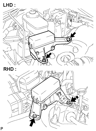
| 14. REMOVE ENGINE ROOM RELAY NO.3 BLOCK |
Remove the bolt, nut and relay No.3 block.
- NOTICE:
- Cover the relay No.3 block with a shop rag or piece of cloth to prevent brake fluid from adhering to it.
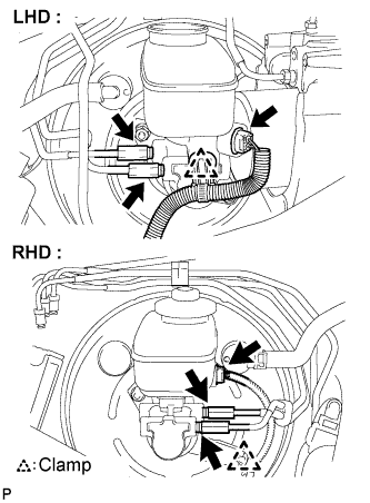
| 15. REMOVE BRAKE MASTER WITH PLATE CYLINDER SUB-ASSEMBLY |
Disengage the clamp and disconnect the warning switch connector.
Using SST, disconnect the 2 brake tubes from the brake master cylinder sub-assembly.
- SST
- 09023-00101
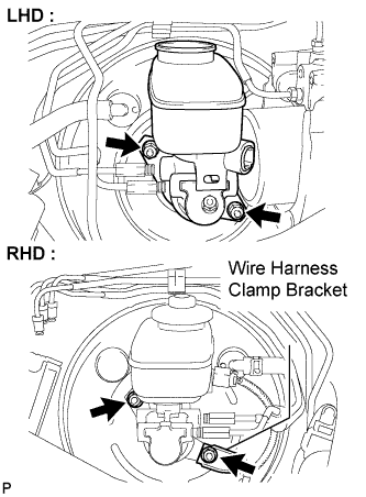
Remove the 2 nuts and brake master cylinder sub-assembly from the brake booster assembly.
Remove the O-ring from the brake master cylinder sub-assembly.
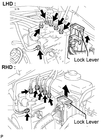
| 16. REMOVE ABS AND TRACTION ACTUATOR ASSEMBLY WITH BRACKET |
Release the lock lever and disconnect the actuator connector.
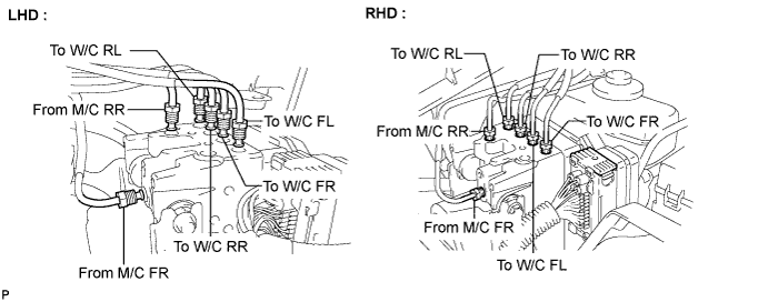
Using SST, disconnect the 6 brake tubes from the actuator assembly with bracket.
- SST
- 09023-00101
Use tags or make a memo to identify the places to reconnect.
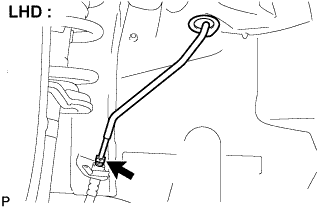
Using SST, disconnect the brake No.2 tube from the flexible hose. (for LHD)
- SST
- 09023-00101
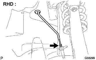
Using SST, disconnect the brake No.2 tube from the flexible hose. (for RHD)
- SST
- 09023-00101
Separate the grommet and remove the brake No.3 tube. (for LHD)
- NOTICE:
- Do not damage the brake No.3 tube.
Separate the grommet and remove the brake No.2 tube. (for RHD)
- NOTICE:
- Do not damage the brake No.2 tube.
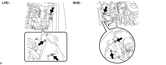
Remove the 2 bolts, nut and actuator assembly from the body with bracket.
- NOTICE:
- Do not damage the brake tubes.
| 17. REMOVE CONSOLE UPPER PANEL GARNISH |
Using a clip remover, detach the claws and remove the garnish.
- HINT:
- Tape the clip remover tip before use.
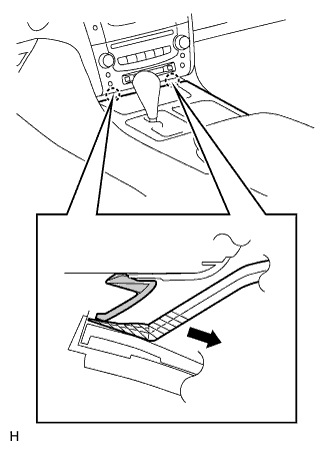
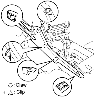
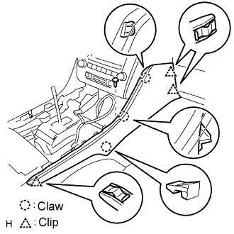
| 18. REMOVE CONSOLE UPPER PANEL SUB-ASSEMBLY |
Twist the shift lever knob in the direction indicated by the arrow and remove it.
Using a screwdriver, detach the 9 clips.
- HINT:
- Tape the screwdriver tip before use.
Remove the ash receptacle and then disconnect the connector.
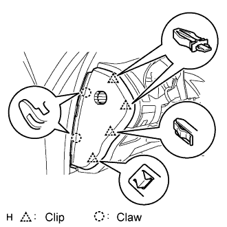
| 19. REMOVE INSTRUMENT PANEL FINISH PANEL END LH (for LHD) |
Remove the screw.
Using a screwdriver, detach the 4 clips and 3 claws.
- HINT:
- Tape the screwdriver tip before use.
Remove the finish panel end.
| 20. REMOVE INSTRUMENT PANEL FINISH PANEL END RH (for RHD) |
Remove the screw.
Using a screwdriver, detach the 3 clips and 3 claws.
- HINT:
- Tape the screwdriver tip before use.
Remove the finish panel end.
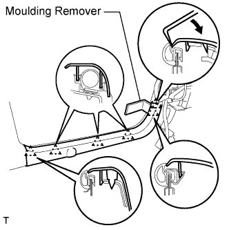
| 21. REMOVE FRONT DOOR SCUFF PLATE LH (for LHD) |
Using a moulding remover, detach the 5 claws and remove the scuff plate.
| 22. REMOVE FRONT DOOR SCUFF PLATE RH (for RHD) |
- HINT:
- Use the same procedures described for the LH side.
| 23. REMOVE FRONT DOOR OPENING TRIM COVER LH (for LHD) |
Using a moulding remover, detach the 3 claws and remove the trim cover.
| 24. REMOVE FRONT DOOR OPENING TRIM COVER RH (for RHD) |
Using a moulding remover, detach the 3 claws and remove the trim cover.
| 25. REMOVE INSTRUMENT SIDE PANEL LH (for LHD) |
Using a screwdriver, detach the 2 claws and 4 clips, and remove the side panel.
- HINT:
- Tape the screwdriver tip before use.
| 26. REMOVE INSTRUMENT SIDE PANEL RH (for RHD) |
Using a screwdriver, detach the 2 claws and 4 clips, and remove the side panel.
- HINT:
- Tape the screwdriver tip before use.
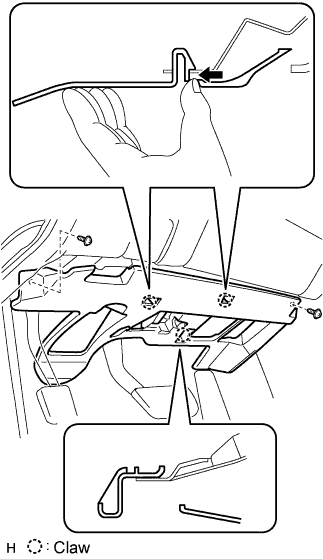
| 27. REMOVE INSTRUMENT PANEL UNDER NO.1 COVER SUB-ASSEMBLY |
Remove the 2 screws.
Detach the 2 claws.
Remove the under cover and then disconnect the connector.
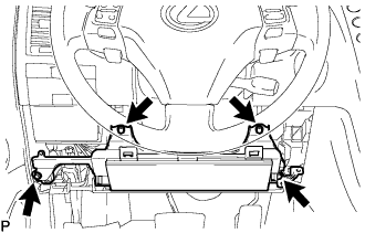
| 28. REMOVE INSTRUMENT PANEL NO.1 SAFETY PAD SUB-ASSEMBLY |
Using a screwdriver, detach the 8 clips and claw.
- HINT:
- Tape the screwdriver tip before use.
Remove the hood lock control cable from the safety pad.
Remove the safety pad.
| 29. REMOVE DRIVER SIDE KNEE AIRBAG ASSEMBLY |
Remove the 4 bolts and driver side knee airbag assembly.
Disconnect the connector.
- NOTICE:
- When handling the airbag connector, take care not to damage the airbag wire harness.
| 30. REMOVE BRAKE PEDAL RETURN SPRING |
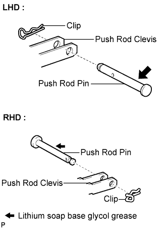
| 31. SEPARATE BRAKE MASTER CYLINDER PUSH ROD CLEVIS |
Remove the clip and the push rod pin, then separate the push rod clevis.
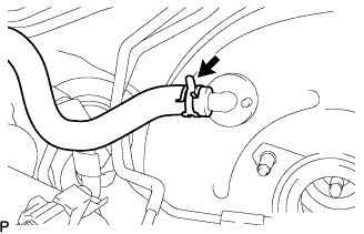
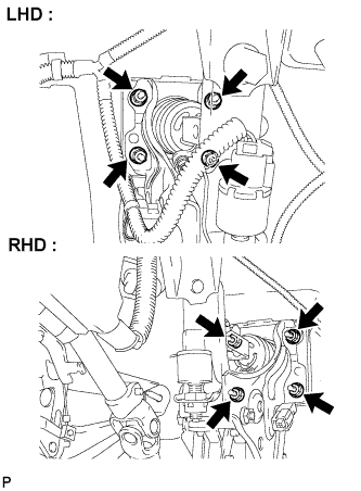
| 32. REMOVE BRAKE BOOSTER ASSEMBLY |
Remove the clip and disconnect the vacuum hose.
Remove the 4 nuts and brake booster assembly.
- NOTICE:
- Do not damage the brake tubes.
| 33. REMOVE BRAKE BOOSTER GASKET |
| 34. REMOVE BRAKE VACUUM CHECK VALVE ASSEMBLY |
Remove the check valve assembly and grommet.
| 35. REMOVE BRAKE MASTER CYLINDER PUSH ROD CLEVIS |
Loosen the lock nut and remove the push rod clevis.