Brake Master Cylinder (W/ Ecb) -- Installation |
| 1. INSTALL BRAKE BOOSTER GASKET |
Install a new gasket to the brake master cylinder assembly with brake simulator assembly.
| 2. INSTALL BRAKE MASTER CYLINDER WITH SIMULATOR CYLINDER ASSEMBLY |
Install the brake master cylinder assembly with brake simulator assembly with the 4 nuts.
- Torque:
- 12.7 N*m{128 kgf*cm, 9 ft.*lbf}
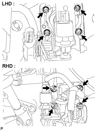 |
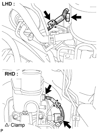
Connect the connectors and clamp.
 |
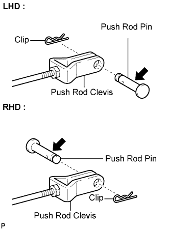
| 3. INSTALL BRAKE MASTER CYLINDER PUSH ROD CLEVIS |
Apply lithium soap base glycol grease to the push rod pin.
Install the push rod clevis to the brake pedal support assembly with the push rod pin and a new clip.
 |
| 4. INSTALL BRAKE PEDAL RETURN SPRING |
Install the brake pedal return spring.
| 5. INSTALL SKID CONTROL ECU BRACKET |
Install the skid control ECU bracket with the 3 bolts.
- Torque:
- 17 N*m{173 kgf*cm, 13 ft.*lbf}
| 6. INSTALL BRAKE ACTUATOR ASSEMBLY WITH ACTUATOR BRACKET |
Install the actuator assembly with bracket to the body with the 2 bolts and nut.
- Torque:
- 19 N*m{195 kgf*cm, 14 ft.*lbf}
- NOTICE:
- Do not damage the brake tubes.
Connect the actuator connector.
- NOTICE:
- Make sure that the connector is locked securely.
Using SST, connect the brake No.1 and No.2 tubes.
- SST
- 09023-00101
- Torque:
- 15 N*m{155 kgf*cm, 11 ft.*lbf}
- NOTICE:
- Do not damage the brake No.1 and No.2 tubes.
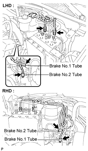 |
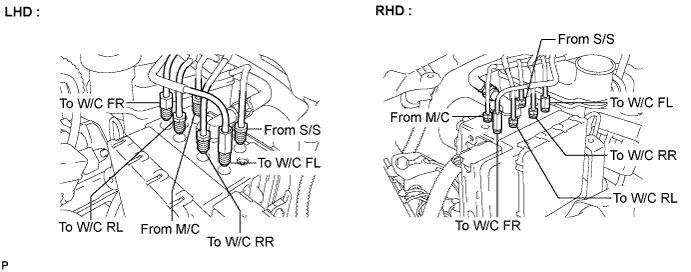
Using SST, connect each brake tube to the correct positions of the actuator assembly with bracket as shown in the illustration.
- SST
- 09023-00101
- Torque:
- 15 N*m{155 kgf*cm, 11 ft.*lbf}
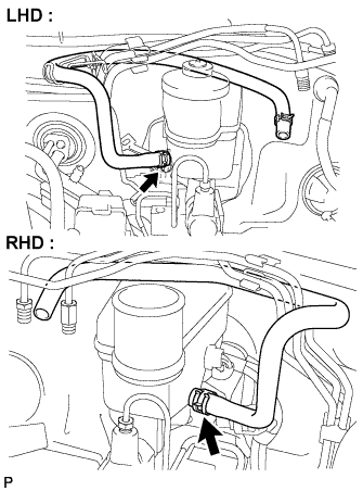
Connect the reservoir No.1 tube with the clip.
| 7. INSTALL RESERVOIR TUBE NO.1 HOSE |
Install the reservoir tube No.1 hose with the clip.
 |
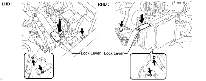
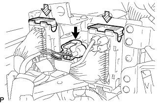
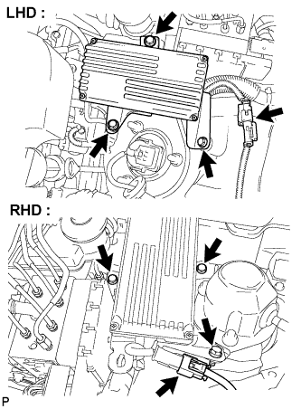
| 8. INSTALL SKID CONTROL ECU ASSEMBLY |
Connect the 3 connectors and press the lock levers down to lock the connectors.
- NOTICE:
- Make sure that the lock levers securely lock the connectors.
 |
Install the skid control ECU assembly with the 3 bolts.
- Torque:
- 17 N*m{173 kgf*cm, 12 ft.*lbf}
 |
Connect the connector.
| 9. CONNECT CABLE TO NEGATIVE BATTERY TERMINAL |
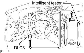
| 10. DISABLE BRAKE CONTROL |
Move the shift lever to the P position and apply the parking brake.
Connect the intelligent tester to the DLC3 with the engine switch off.
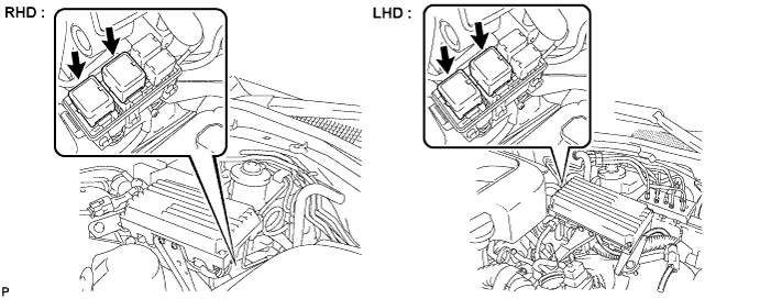
 |
Remove the 2 ABS motor relays with the engine switch off from the engine room relay block No.3.
Turn the engine switch on (IG).
- NOTICE:
- Do not start the engine.
Turn the intelligent tester on and select "DIAGNOSTIC MENU"→"ABS/VSC"→"ECB UTILITY"→"ECB INVALID".
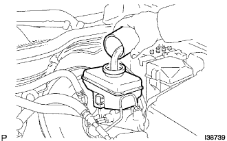
| 11. FILL RESERVOIR WITH BRAKE FLUID |
- NOTICE:
- If brake fluid leaks onto any painted surface, clean it off completely.
Add brake fluid into the reservoir.
- Fluid:
- SAE J1703 or FMVSS No.116 DOT3
 |
| 12. BLEED BRAKE RESERVOIR TUBE NO.1 HOSE |
Connect SST to the reservoir with the brake reservoir pressure adapter.
- SST
- 09992-00242
09992-00350
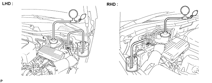
Connect the vinyl tube to the bleeder plug of the actuator.
Loosen the bleeder plug of the actuator.
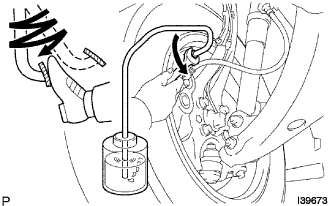
Use the SST to boost the pressure in the reservoir.
- Standard:
- 50 to 80 kPa (0.5 to 0.8 kgf/cm2,7.3 to 11.6 psi)
Drain approximately 100 cc of fluid.
Tighten the bleeder plug and boost the pressure in the reservoir again. Then loosen the bleeder plug to bleed air.
- NOTICE:
- Repeat the above procedures 5 times or more.
When air is completely bled from the hose between the reservoir and the actuator, tighten the bleeder plug.
- Torque:
- 8.3 N*m{85 kgf*cm, 74 ft.*lbf}
| 13. BLEED MASTER CYLINDER |
- HINT:
- If the master cylinder has been reinstalled or if the reservoir becomes empty, bleed the air from the master cylinder.
Disconnect the brake lines from the master cylinder.
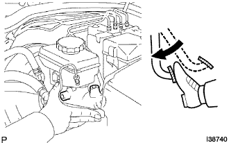 |
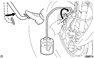
Slowly depress and hold the brake pedal.
Cover the outer holes with fingers, and release the brake pedal.
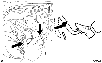 |
Repeat (b) and (c) 3 or 4 times.
Connect the brake lines to the master cylinder.
- Torque:
- 15 N*m{155 kgf*cm, 11 ft.*lbf}
| 14. BLEED FRONT BRAKE SYSTEM |
- NOTICE:
- Bleed the air from the wheel furthest from the master cylinder.
Connect the vinyl tube to the bleeder plug.
 |
Depress the brake pedal several times, then loosen the bleeder plug with the pedal depressed.
When fluid stops coming out, tighten the bleeder plug, then release the brake pedal.
 |
Repeat (b) and (c) until all the air in the fluid is completely bled out.
Using SST, tighten the bleeder plug completely.
- Torque:
- 11 N*m{112 kgf*cm, 8 ft.*lbf}
Repeat the above procedures for other wheels to bleed the air from the brake line.
| 15. BLEED REAR BRAKE SYSTEM |
- NOTICE:
- Bleed the air by following the prompts displayed on the intelligent tester.
Turn the engine switch off.
Install the 2 ABS motor relays to the engine room relay block No.3.
- NOTICE:
- Install ABS motor relays before bleeding the air from the rear brake system.
Turn the engine switch on (IG) and turn the intelligent tester on.
Cancel "DISABLE BRAKE CONTROL" on the intelligent tester.
- HINT:
- If the brake control has been disabled by the tester.
Clear the DTC.
Turn the intelligent tester on and select "DIAGNOSTIC MENU"→"ABS/VSC"→"ECB UTILITY"→"ECB INVALID".
With the brake pedal depressed, bleed air from the bleeder plug on the rear disc brake cylinder LH.
- NOTICE:
- Keep the fluid inside the reservoir above the LOW level by replenishing.
- HINT:
- Depress and hold the brake pedal.
- After the solenoid operates for approximately 30 seconds, release the brake pedal to stop the solenoid.
- Repeat the procedures until air is completely bled from the rear brake system.
- The ECB warning light comes on and the buzzer sounds while bleeding, but they do not indicate a malfunction.
- Torque:
- 11 N*m{112 kgf*cm, 8 ft.*lbf}
Tighten the bleeder plug after bleeding.
With the brake pedal depressed, bleed air from the bleeder plug on the rear disc brake cylinder RH.
- NOTICE:
- Keep the fluid inside the reservoir above the LOW level by replenishing.
- HINT:
- Depress and hold the brake pedal.
- After the solenoid operates for approximately 30 seconds, release the brake pedal to stop the solenoid
- Repeat the procedures until air is completely bled from the rear brake system.
- The ECB warning light comes on and the buzzer sounds while bleeding, but they do not indicate a malfunction.
Tighten the bleeder plug after bleeding.
- Torque:
- 11 N*m{112 kgf*cm, 8 ft.*lbf}
Cancel "DISABLE BRAKE CONTROL" on the intelligent tester.
| 16. PERFORM ACCUMULATOR ZERO DOWN |
- CAUTION:
- Be sure to perform this procedure before removing of the actuator.
- NOTICE:
- Perform accumulator zero down by following the prompts displayed on the intelligent tester.
Connect the intelligent tester to the DLC3 with the engine switch off.
Turn the intelligent tester on and repeat the following steps 5 times.
Turn the engine switch on (IG).
Turn the intelligent tester on and select "DIAGNOSTIC MENU" → "ABS/VSC" → "ECB UTILITY" → "ZERO DOWN" on the intelligent tester.
When the buzzer sounds, turn the engine switch off.
- NOTICE:
- Keep the fluid inside the reservoir above the LOW level by replenishing.
- HINT:
- Accumulator pressure is released and accumulated repeatedly, which circulates the fluid inside the accumulator every time accumulator zero down (accumulator depressurizing) is performed.
- The pump motor rotates and accumulator is pressurized every time the engine switch is turned from off to on (IG).
| 17. CHECK BRAKE FLUID LEVEL |
After performing accumulator zero down (accumulator depressurizing), adjust the fluid level in the master cylinder reservoir to the MAX level.
- HINT:
- After performing accumulator zero down (accumulator depressurizing), fluid is built up in the accumulator by turning the engine switch on (IG) and the fluid level lowers.
- If the fluid level is adjusted without performing accumulator zero down (accumulator depressurizing), fluid is sent from the accumulator to the reservoir. The fluid level may exceed the MAX level, but it is normal.
| 18. CLEAR DTC |
| 19. PERFORM LINEAR VALVE OFFSET LEARNING |
When the brake actuator assembly is replaced, perform linear valve offset learning. (Click here)
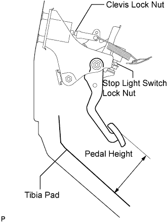
| 20. INSPECT BRAKE PEDAL HEIGHT |
Check the brake pedal height.
- Pedal height from tibia pad :
- 120.5 to 130.5 mm (4.744 to 5.138 in.)
 |
Adjust brake pedal height.
Disconnect the connector from the stop light switch assembly.
Remove the stop light switch lock nut. Turn the switch in order to give the pedal some free play.
for VSC :
Remove the brake booster assembly.for ECB :
Remove brake master cylinder with simulator assembly.for VSC :
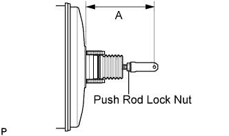
Loosen the push rod lock nut, turn the push rod clevis and adjust length "A" shown in the illustration.- Length "A":
- 146.2 to 147.2 mm (5.756 to 5.795 in.)
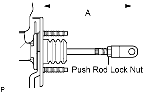
for ECB :
Loosen the push rod lock nut, turn the push rod clevis and adjust length "A" shown in the illustration.- Length "A":
- 147.5 to 148.5 mm (5.807 to 5.846 in.)
Tighten the push rod lock nut.
- Torque:
- 26 N*m{265 kgf*cm, 19 ft.*lbf}
for VSC :
Install the brake booster assembly.for ECB :
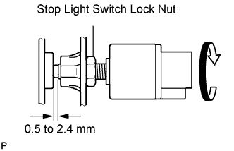
Install the brake master cylinder with simulator assembly.Turn the stop light switch assembly so that the clearance between the switch and the area where the pedal makes contact is between 0.5 and 2.4 mm (0.020 to 0.095 in.). Tighten the lock nut.
- Torque:
- 17 N*m{170 kgf*cm, 12 ft.*lbf}
Connect the connector to the stop light switch assembly.
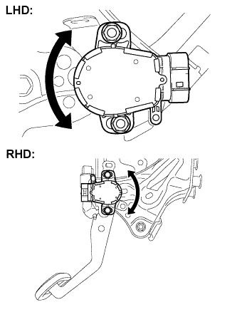
Adjust the brake pedal stroke sensor.
Connect the intelligent tester to the DLC3.
Loosen the 2 nuts. (for LHD)
Loosen the 2 bolts. (for RHD)
Turn the engine switch on (IG). Reading the stroke sensor 1 value shown on the data monitor, turn the stroke sensor slowly to the right and left to adjust it to the standard voltage.
- Standard voltage:
- 0.8 to 1.2 V
- NOTICE:
- Do not depress the brake pedal after turning the engine switch on (IG).
Tighten the 2 nuts. (for LHD)
- Torque:
- 8.5 N*m{87 kgf*cm, 75 in.*lbf}
Tighten the 2 bolts. (for RHD)
- Torque:
- 8.5 N*m{87 kgf*cm, 75 in.*lbf}
Perform system initialization.
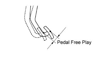
| 21. INSPECT PEDAL FREE PLAY |
Stop the engine and depress the brake pedal several times until no vacuum is left in the booster.
Press the pedal until a slight resistance is felt. Measure the distance as shown in the illustration.
- Pedal free play:
- 1.0 to 2.0 mm (0.039 to 0.079 in.)
- Protrusion of the stop light switch assembly shaft:
- 0.5 to 2.4 mm (0.020 to 0.095 in.)
If the protrusion is within the specified value range, it is normal though brake pedal free play is 1.0 mm (0.039 in.) or less.
 |
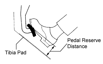
| 22. INSPECT PEDAL RESERVE DISTANCE |
Release the parking brake pedal.
With the engine running, depress the pedal and measure the pedal reserve distance as shown in the illustration.
- Pedal reserve distance from tibia pad at 490 N (50 kgf, 110 lbf) for VSC:
- More than 69 mm (2.71 in.)
- Pedal reserve distance from tibia pad at 196 N (20 kgf, 44 lbf) for ECB:
- More than 86 mm (3.38 in.)
 |
| 23. INSPECT BRAKE FLUID LEAKAGE |
| 24. INSTALL DRIVER SIDE KNEE AIRBAG ASSEMBLY |
Connect the connector.
- NOTICE:
- When handling the airbag connector, take care not to damage the airbag wire harness.
 |
Install the driver side knee airbag assembly with the 4 bolts.
- Torque:
- 10 N*m{102 kgf*cm, 7 ft.*lbf}
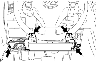
| 25. INSTALL INSTRUMENT PANEL SAFETY PAD SUB-ASSEMBLY |
 |
Install the hood lock control cable to the safety pad.
Attach the 8 clips and claw to install the safety pad.
| 26. INSTALL INSTRUMENT PANEL UNDER COVER NO.1 SUB-ASSEMBLY |
 |
Connect the connectors.
Attach the 2 claws to install the under cover.
Install the 2 screws.
| 27. INSTALL INSTRUMENT SIDE PANEL LH (for LHD) |
 |
Attach the 2 claws and 4 clips to install the side panel.
| 28. INSTALL INSTRUMENT SIDE PANEL RH (for RHD) |
 |
Attach the 2 claws and 4 clips to install the side panel.
| 29. INSTALL FRONT DOOR OPENING TRIM COVER LH (for LHD) |
Attach the 3 claws to install the trim cover.
Pull out the folded lip of the weatherstrip.
| 30. INSTALL FRONT DOOR OPENING TRIM COVER RH (for RHD) |
- HINT:
- Use the same procedures described for the LH side.
| 31. INSTALL FRONT DOOR SCUFF PLATE LH (for LHD) |
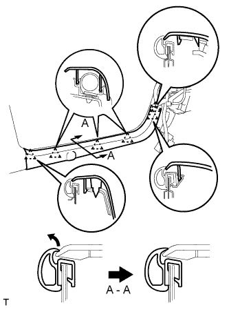 |
Attach the 5 claws to install the scuff plate.
Pull out the folded lip of the weatherstrip.
| 32. INSTALL FRONT DOOR SCUFF PLATE RH (for RHD) |
- HINT:
- Use the same procedures described for the LH side.
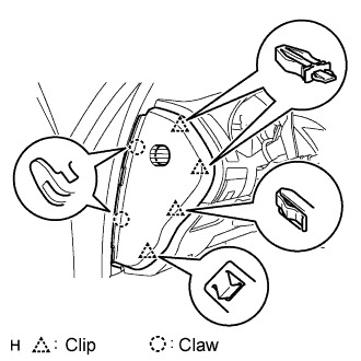
| 33. INSTALL INSTRUMENT PANEL FINISH PANEL END LH (for LHD) |
 |
Attach the 4 clips and 3 claws to install the finish panel end.
Install the screw.
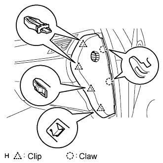
| 34. INSTALL INSTRUMENT PANEL FINISH PANEL END RH (for RHD) |
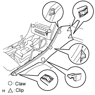 |
Attach the 3 clips and 3 claws to install the finish panel end.
Install the screw.
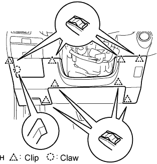
| 35. INSTALL CONSOLE UPPER PANEL SUB-ASSEMBLY |
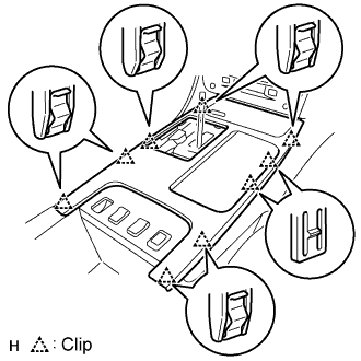 |
Connect the connector.
Attach the 9 clips to install the ash receptacle.
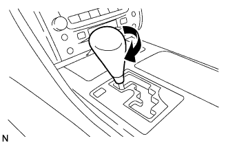
Install the shift lever knob and twist it in the direction indicated by the arrow.
 |
| 36. INSTALL CONSOLE UPPER PANEL GARNISH |
Attach the claws to install the garnish.
| 37. INSTALL FRONT WHEEL |
- Torque:
- 103 N*m{1,050 kgf*cm, 76 ft.*lbf}
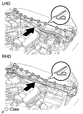
| 38. INSTALL COWL TOP VENTILATOR LOUVER SUB-ASSEMBLY |
Push the ventilator louver in the direction indicated by the arrow in the illustration. Attach the 10 claws to install the ventilator louver.
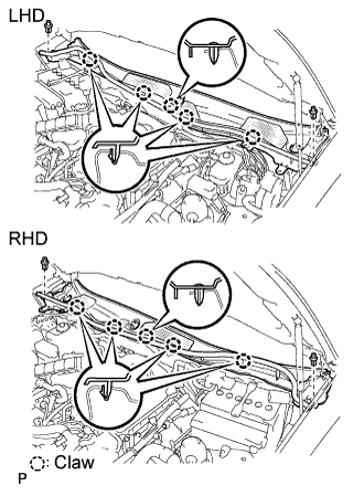
 |
Attach the 5 claws and 2 clips to install the ventilator louver.
 |
| 39. INSTALL FRONT FENDER TO COWL SIDE SEAL LH |
Push the cowl side seal in the direction indicated by the arrow in the illustration. Attach the 2 claws to install the cowl side seal.
 |
| 40. INSTALL FRONT FENDER TO COWL SIDE SEAL RH |
- HINT:
- Use the same procedures described for the LH side.
| 41. INSTALL FRONT WIPER ARM AND BLADE ASSEMBLY LH |
 |
Stop the wiper motor at the automatic stop position.
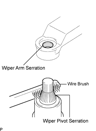
Clean the wiper arm serration with a round file or equivalent.
Clean the wiper pivot serration with a wire brush.
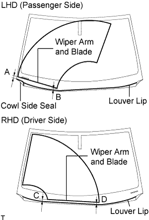
Install the wiper arm and blade with the nut. Make sure that the wiper arm and blade comes to the position shown in the illustration.
- Torque:
- 22 N*m{224 kgf*cm, 16 ft.*lbf}
- HINT:
- Hold down the wiper arm hinge with your hand while tightening the nut.
- Specification:
Area Measurement A (for LHD) 25.3 mm (0.996 in.) B (for LHD) 26.2 mm (1.031 in.) C (for RHD) 21.8 mm (0.858 in.) D (for RHD) 28.9 mm (1.138 in.)
 |
| 42. INSTALL FRONT WIPER ARM AND BLADE ASSEMBLY RH |
|
Stop the wiper motor at the automatic stop position.
Clean the wiper arm serration with a round file or equivalent.
Clean the wiper pivot serration with a wire brush.
Install the wiper arm and blade with the nut. Make sure that the wiper arm and blade comes to the position shown in the illustration.
- Torque:
- 22 N*m{224 kgf*cm, 16 ft.*lbf}
- HINT:
- Hold down the wiper arm hinge with your hand while tightening the nut.
- Specification:
Area Measurement A (for LHD) 28.9 mm (1.138 in.) B (for LHD) 21.8 mm (0.858 in.) C (for RHD) 26.2 mm (1.031 in.) D (for RHD) 25.3 mm (0.996 in.)
 |
Operate the front wipers while spraying washer fluid on the windshield glass. Make sure that the front wipers function properly and there is no interference with the vehicle body.
| 43. INSTALL FRONT PILLAR TO FRONT SIDE SEAL SUB-ASSEMBLY RH |
 |
Attach the 3 clips to install the side seal.
| 44. INSTALL FRONT PILLAR TO FRONT SIDE SEAL SUB-ASSEMBLY LH |
- HINT:
- Use the same procedures described for the LH side.
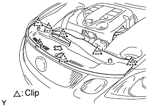
| 45. INSTALL ENGINE ROOM SIDE COVER RH |
Install the side cover with the 2 clips and nut.
 |
| 46. INSTALL ENGINE ROOM SIDE COVER LH |
Install the side cover with the 3 clips.
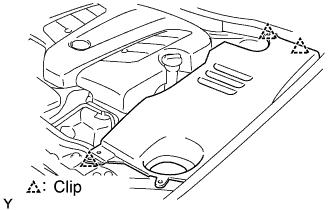 |
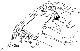
| 47. INSTALL COOL AIR INTAKE DUCT SEAL |
 |
Install the intake duct seal with the 7 clips.
| 48. INSPECT VSC SENSOR SIGNAL |
| 49. INSPECT ACTUATOR WITH INTELLIGENT TESTER |
| 50. INSPECT SRS WARNING LIGHT |
| 51. CLEAR DTC |