Brake Master Cylinder (W/ Vsc) -- Installation |
| 1. INSTALL BRAKE MASTER WITH PLATE CYLINDER SUB-ASSEMBLY |
Install a new O-ring to the brake master cylinder sub-assembly.
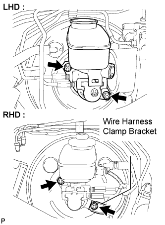
Install the brake master cylinder sub-assembly to the booster assembly with the 2 nuts.
- Torque:
- 12.5 N*m{127 kgf*cm, 9 ft.*lbf}
 |
Using SST, connect the 2 brake tubes to the brake master cylinder sub-assembly.
- SST
- 09023-00101
- Torque:
- 15 N*m{155 kgf*cm, 11 ft.*lbf}
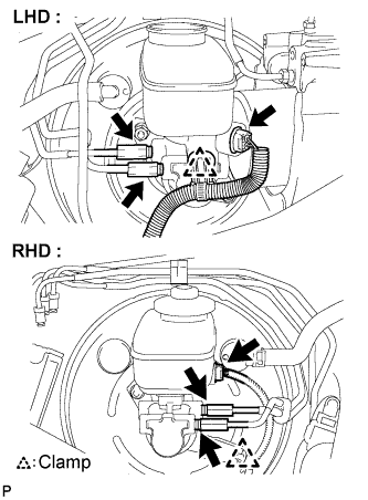 |
Engage the clamp and connect the warning switch connector.
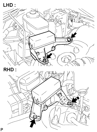
| 2. INSTALL ENGINE ROOM RELAY NO.3 BLOCK |
Install the relay block No.3 with the bolt and nut.
- Torque:
- 12.5 N*m{127 kgf*cm, 9 ft.*lbf}
 |
| 3. FILL RESERVOIR WITH BRAKE FLUID |
Fill reservoir with brake fluid.
- Fluid:
- SAE J1703 or FMVSS No. 116 DOT3
 |
| 4. BLEED MASTER CYLINDER |
- HINT:
- If the master cylinder is reinstalled or if the reservoir becomes empty, bleed the air from the master cylinder.
- To avoid brake fluid from adhering, cover the painted surface with a shop rag or a piece of cloth.
Disconnect the 2 brake lines from the master cylinder.
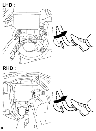
Slowly depress the brake pedal and hold it.
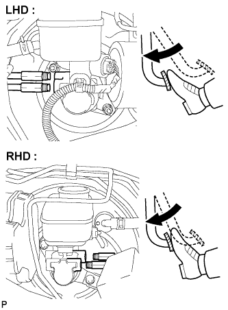 |
Cover the 2 outer holes with fingers, and release the brake pedal.
 |
Repeat (b) and (c) 3 or 4 times.
Using SST, connect the brake lines to the master cylinder.
- SST
- 09023-00101
- Torque:
- 15 N*m{155 kgf*cm, 11 ft.*lbf}
| 5. BLEED BRAKE LINE |
- NOTICE:
- Bleed the air from the wheel furthest from the master cylinder.
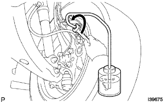
Connect a vinyl tube to the bleeder plug.
Depress the brake pedal several times, then loosen the bleeder plug with the pedal depressed.
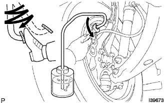 |
When fluid stops coming out, tighten the bleeder plug, then release the brake pedal.
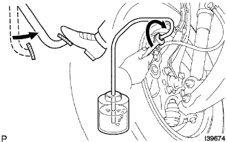 |
Repeat (b) and (c) until all the air in the fluid is completely bled out.
Using SST, tighten the bleeder plug completely.
- SST
- 09023-00101
- Torque:
- 11 N*m{112 kgf*cm, 8 ft.*lbf}
Repeat the above procedures for each wheel to bleed the air from the brake line.
| 6. BLEED ABS AND TRACTION ACTUATOR ASSEMBLY |
- NOTICE:
- After bleeding the air from the brake system, if the height or feel of the brake pedal cannot be obtained, bleed the air from the ABS and TRACTION actuator assembly with the intelligent tester by following the procedures below.
Depress the brake pedal more than 20 times with the engine switch off.
Connect the intelligent tester to the DLC3, then turn the engine switch on (IG).
- NOTICE:
- Do not start the engine.
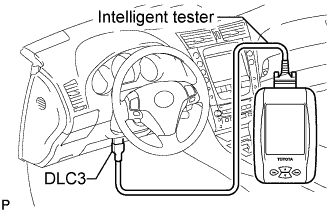 |
Turn the intelligent tester on and select "AIR BLEEDING" on the screen.
- NOTICE:
- Refer to the intelligent tester operator's manual for further details.
- Bleed the air by following the prompts displayed on the intelligent tester.
Bleed the air according to "Step 1: Increase" on the intelligent tester display.
- NOTICE:
- Make sure that the master cylinder reservoir tank does not become empty of brake fluid.
Connect a vinyl tube to either one of the bleeder plugs.
Depress the brake pedal several times, then loosen the bleeder plug connected to the vinyl tube with the pedal depressed.
When fluid stops coming out, tighten the bleeder plug, then release the brake pedal.
Repeat (2) and (3) until all the air in the fluid is completely bled out.
Using SST, tighten the bleeder plug completely.
- Torque:
- 11 N*m{112 kgf*cm, 8 ft.*lbf}
- SST
- 09023-00101
Repeat the above procedures for the rest of the wheels to bleed the air from the brake line.
Bleed the air from the suction line according to "Step 2: Inhalation" on the intelligent tester display.
- NOTICE:
- Bleed the suction line by following the prompts displayed on the intelligent tester.
- Make sure that the master cylinder reservoir tank does not become empty of brake fluid.
Connect a vinyl tube to the bleeder plug at the right front wheel or the right rear wheel and loosen the bleeder plug.
Operate the ABS and TRACTION actuator assembly to bleed the air using the intelligent tester.
- NOTICE:
- The operation stops automatically in 4 seconds.
- At this time, be sure to release the brake pedal.
Check that the operation has stopped by referring to the intelligent tester display and tighten the bleeder plug.
Repeat (2) and (3) until all the air in the fluid is completely bled out.
Using SST, tighten the bleeder plug completely.
- Torque:
- 11 N*m{112 kgf*cm, 8 ft.*lbf}
- SST
- 09023-00101
For the rest of the wheels, bleed the air in the same way as stated in the above procedures.
Bleed the air from the pressure reduction line according to "Step 3: Decrease" on the intelligent tester display.
- NOTICE:
- Bleed the pressure reduction line by following the prompts displayed on the intelligent tester.
- Make sure that the master cylinder reservoir tank does not become empty of brake fluid.
Connect a vinyl tube to either one of the bleeder plugs.
Loosen the bleeder plug.
Using the intelligent tester, operate the ABS and TRACTION actuator assembly, completely depress the brake pedal and hold it.
- NOTICE:
- The operation stops automatically in 4 seconds. When performing this procedure continuously, an interval of at least 20 seconds is required.
- When the operation is completed, the brake pedal slightly goes down. This is a normal phenomenon when the solenoid opens.
- During this procedure, the pedal seems heavy, but completely depress it so that the brake fluid comes out from the bleeder plug.
- Be sure to keep the brake pedal depressed. Never depress and release the pedal repeatedly.
Tighten the bleeder plug, then release the brake pedal.
Repeat (2) to (4) until all the air in the fluid is completely bled out.
Using SST, tighten the bleeder plug completely.
- Torque:
- 11 N*m{112 kgf*cm, 8 ft.*lbf}
- SST
- 09023-00101
Repeat the above procedures for the rest of the brakes to bleed the air from the brake line.

Bleed the air from the brake line again according to "Step 4: Increase" on the intelligent tester display.
- NOTICE:
- Bleed the air from the brake line again according to "Step 4: Increase" on the intelligent tester display.
- Make sure that the master cylinder reservoir tank does not become empty of brake fluid.
Connect a vinyl tube to either one of the bleeder plugs.
Depress the brake pedal several times, then loosen the bleeder plug connected to the vinyl tube with the pedal depressed.
When fluid stops coming out, tighten the bleeder plug, then release the brake pedal.
Repeat (2) and (3) until all the air in the fluid is completely bled out.
Using SST, tighten the bleeder plug completely.
- Torque:
- 11 N*m{112 kgf*cm, 8 ft.*lbf}
- SST
- 09023-00101
Repeat the above procedures for each brake to bleed the air from the brake line.
Finish "AIR BLEEDING" on the intelligent tester and turn off the power.
Disconnect the intelligent tester from the DLC3.
Turn the engine switch off.
| 7. INSTALL FRONT WHEEL |
- Torque:
- 103 N*m{1,050 kgf*cm, 76 ft.*lbf}
| 8. CHECK FLUID LEVEL IN RESERVOIR |
Check the fluid level and add fluid if necessary.
- Fluid:
- SAE J1703 or FMVSS No. 116 DOT3
| 9. INSPECT BRAKE FLUID LEAKAGE |
| 10. CLEAR DTC |
| 11. CHECK VSC SENSOR SIGNAL |
| 12. CHECK ACTUATOR WITH INTELLIGENT TESTER |
| 13. INSTALL COWL TOP VENTILATOR LOUVER SUB-ASSEMBLY |
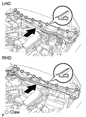
Push the ventilator louver in the direction indicated by the arrow in the illustration. Attach the 10 claws to install the ventilator louver.
 |
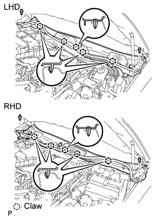
Attach the 5 claws and 2 clips to install the ventilator louver.
 |
| 14. INSTALL FRONT FENDER TO COWL SIDE SEAL LH |
Push the cowl side seal in the direction indicated by the arrow in the illustration. Attach the 2 claws to install the cowl side seal.
 |
| 15. INSTALL FRONT FENDER TO COWL SIDE SEAL RH |
- HINT:
- Use the same procedures described for the LH side.
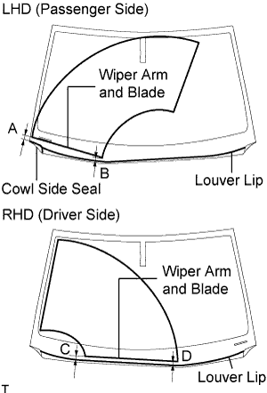
| 16. INSTALL FRONT WIPER ARM AND BLADE ASSEMBLY LH |
 |
Stop the wiper motor at the automatic stop position.
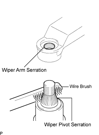
Clean the wiper arm serration with a round file or equivalent.
Clean the wiper pivot serration with a wire brush.
Install the wiper arm and blade with the nut. Make sure that the wiper arm and blade comes to the position shown in the illustration.
- Torque:
- 22 N*m{224 kgf*cm, 16 ft.*lbf}
- HINT:
- Hold down the wiper arm hinge with your hand while tightening the nut.
- Specification:
Area Measurement A (for LHD) 25.3 mm (0.996 in.) B (for LHD) 26.2 mm (1.031 in.) C (for RHD) 21.8 mm (0.858 in.) D (for RHD) 28.9 mm (1.138 in.)
 |
| 17. INSTALL FRONT WIPER ARM AND BLADE ASSEMBLY RH |
|
Stop the wiper motor at the automatic stop position.
Clean the wiper arm serration with a round file or equivalent.
Clean the wiper pivot serration with a wire brush.
Install the wiper arm and blade with the nut. Make sure that the wiper arm and blade comes to the position shown in the illustration.
- Torque:
- 22 N*m{224 kgf*cm, 16 ft.*lbf}
- HINT:
- Hold down the wiper arm hinge with your hand while tightening the nut.
- Specification:
Area Measurement A (for LHD) 28.9 mm (1.138 in.) B (for LHD) 21.8 mm (0.858 in.) C (for RHD) 26.2 mm (1.031 in.) D (for RHD) 25.3 mm (0.996 in.)
 |
Operate the front wipers while spraying washer fluid on the windshield glass. Make sure that the front wipers function properly and there is no interference with the vehicle body.
| 18. INSTALL FRONT PILLAR TO FRONT SIDE SEAL SUB-ASSEMBLY LH |
 |
Attach the 3 clips to install the side seal.
| 19. INSTALL FRONT PILLAR TO FRONT SIDE SEAL SUB- ASSEMBLY RH |
- HINT:
- Use the same procedures described for the LH side.
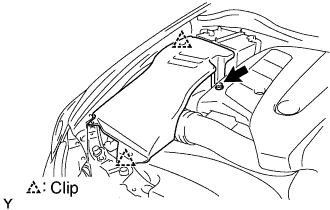
| 20. INSTALL ENGINE ROOM SIDE COVER RH |
Install the side cover with the 2 clips and nut.
 |
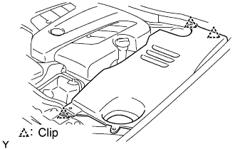
| 21. INSTALL ENGINE ROOM SIDE COVER LH |
Install the side cover with the 3 clips.
 |
| 22. INSTALL COOL AIR INTAKE DUCT SEAL |
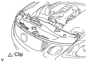 |
Install the intake duct seal with the 7 clips.