Brake Pedal -- Adjustment |
| 1. INSPECT AND ADJUST BRAKE PEDAL HEIGHT |
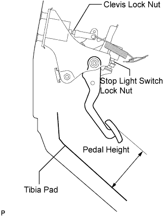
Check the brake pedal height.
- Pedal height from tibia pad :
- 120.5 to 130.5 mm (4.744 to 5.138 in.)
 |
Adjust brake pedal height.
Disconnect the connector from the stop light switch assembly.
Remove the stop light switch lock nut. Turn the switch in order to give the pedal some free play.
for VSC :
Remove the brake booster assembly.for ECB :
Remove brake master cylinder with simulator assembly.for VSC :
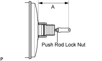
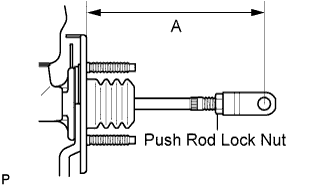
Loosen the push rod lock nut, turn the push rod clevis and adjust length "A" shown in the illustration.- Length "A":
- 146.2 to 147.2 mm (5.756 to 5.795 in.)
for ECB :
Loosen the push rod lock nut, turn the push rod clevis and adjust length "A" shown in the illustration.- Length "A":
- 147.5 to 148.5 mm (5.807 to 5.846 in.)
Tighten the push rod lock nut.
- Torque:
- 26 N*m{265 kgf*cm, 19 ft.*lbf}
for VSC :
Install the brake booster assembly.for ECB :
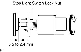
Install the brake master cylinder with simulator assembly.Turn the stop light switch assembly so that the clearance between the switch and the area where the pedal makes contact is between 0.5 and 2.4 mm (0.020 to 0.095 in.). Tighten the lock nut.
- Torque:
- 17 N*m{170 kgf*cm, 12 ft.*lbf}
Connect the connector to the stop light switch assembly.
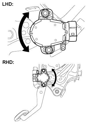
Adjust the brake pedal stroke sensor.
Connect the intelligent tester to the DLC3.
Loosen the 2 nuts. (for LHD)
Loosen the 2 bolts. (for RHD)
Turn the engine switch on (IG). Reading the stroke sensor 1 value shown on the data monitor, turn the stroke sensor slowly to the right and left to adjust it to the standard voltage.
- Standard voltage:
- 0.8 to 1.2 V
- NOTICE:
- Do not depress the brake pedal after turning the engine switch on (IG).
Tighten the 2 nuts. (for LHD)
- Torque:
- 8.5 N*m{87 kgf*cm, 75 in.*lbf}
Tighten the 2 bolts. (for RHD)
- Torque:
- 8.5 N*m{87 kgf*cm, 75 in.*lbf}
Perform system initialization.
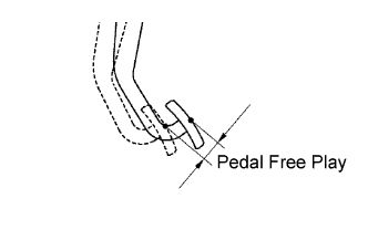
| 2. INSPECT PEDAL FREE PLAY |
Stop the engine and depress the brake pedal several times until no vacuum is left in the booster.
Press the pedal until a slight resistance is felt. Measure the distance as shown in the illustration.
- Pedal free play:
- 1.0 to 2.0 mm (0.039 to 0.079 in.)
- Protrusion of the stop light switch assembly shaft:
- 0.5 to 2.4 mm (0.020 to 0.095 in.)
If the protrusion is within the specified value range, it is normal though brake pedal free play is 1.0 mm (0.039 in.) or less.
 |
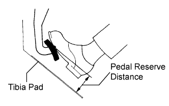
| 3. INSPECT PEDAL RESERVE DISTANCE |
Release the parking brake pedal.
With the engine running, depress the pedal and measure the pedal reserve distance as shown in the illustration.
- Pedal reserve distance from tibia pad at 490 N (50 kgf, 110 lbf) for VSC:
- More than 69 mm (2.71 in.)
- Pedal reserve distance from tibia pad at 196 N (20 kgf, 44 lbf) for ECB:
- More than 86 mm (3.38 in.)
 |