Dtc P0660 Intake Manifold Tuning Valve Control Circuit / Open (Bank 1)
Engine. Lexus Gs430, Gs300. Uzs190 Grs190
DESCRIPTION
WIRING DIAGRAM
INSPECTION PROCEDURE
PERFORM ACTIVE TEST (VACUUM SWITCHING VALVE)
CHECK VACUUM HOSES (INTAKE MANIFOLD - VACUUM SWITCHING VALVE, VACUUM SWITCHING VALVE - INTAKE AIR CONTROL VALVE)
INSPECT INTAKE AIR CONTROL VALVE
INSPECT VACUUM SWITCHING VALVE (OPERATION)
CHECK WIRE HARNESS (VACUUM SWITCHING VALVE - ECM, VACUUM SWITCHING VALVE)
INSPECT INTEGRATION RELAY (EFI MAIN RELAY)
DTC P0660 Intake Manifold Tuning Valve Control Circuit / Open (Bank 1) |
DESCRIPTION
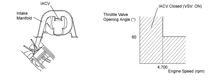
This circuit opens and closes the Intake Air Control Valve (IACV) in response to the engine load in order to increase the intake efficiency (ACIS: Acoustic Control Induction System).When the engine speed is 4,700 rpm or more and the throttle valve opening angle is 60° or more, the IACV is open (VSV: OFF). At all other times, the IACV is closed (VSV: ON).DTC No.
| DTC Detection Condition
| Trouble Area
|
P0660
| Proper response to ECM command does not occur (2 trip detection logic)
| - Open or short in ACIS VSV circuit
- ACIS VSV
- ECM
|
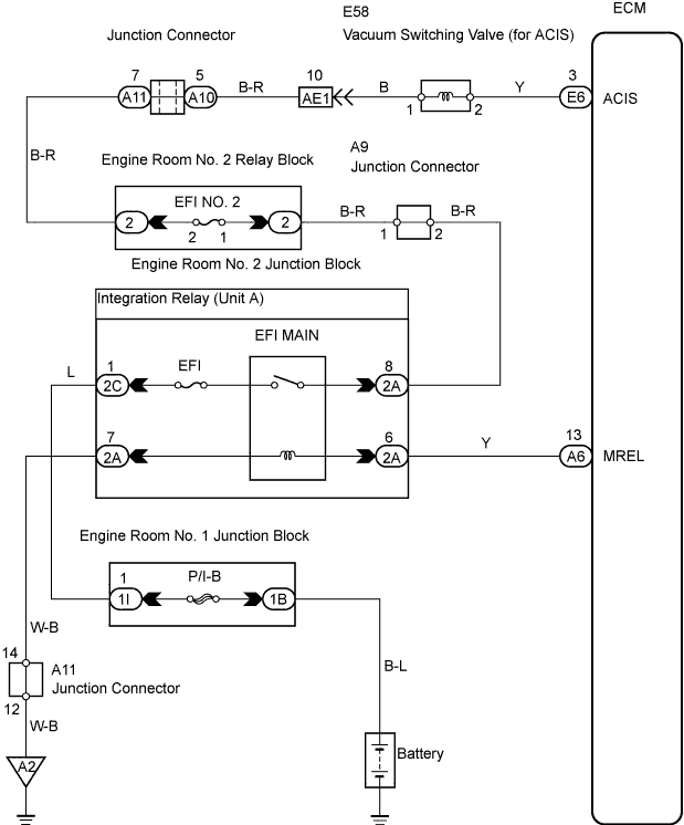
WIRING DIAGRAM
INSPECTION PROCEDURE
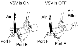
| 1.PERFORM ACTIVE TEST (VACUUM SWITCHING VALVE) |
Disconnect the vacuum hose from the port F on the vacuum switching valve (for ACIS).
Connect the intelligent tester to the DLC3.
Start the engine.
Enter the following menus: Powertrain / Engine / Active Test / Activate the VSV for Intake Control. Operate the ACIS VSV.
Check the VSV's air flow when switching the VSV.
- OK:
Tester Condition
| Specified Condition
|
VSV is ON
| Air from port E flows out through port F
|
VSV is OFF
| Air from port E flows out through the air filter
|
| 2.CHECK VACUUM HOSES (INTAKE MANIFOLD - VACUUM SWITCHING VALVE, VACUUM SWITCHING VALVE - INTAKE AIR CONTROL VALVE) |
Check the condition of the vacuum hoses between the intake manifold, vacuum switching valve (for ACIS) and IACV.
The vacuum hoses are connected securely.
Vacuum hoses are not cranked or damaged.
- OK:
- The vacuum hoses are connected securely and not cracked or damaged.
| | REPAIR OR REPLACE VACUUM HOSES |
|
|
| 3.INSPECT INTAKE AIR CONTROL VALVE |
Inspect the intake air control valve (Click here).
| | REPLACE INTAKE AIR CONTROL VALVE |
|
|
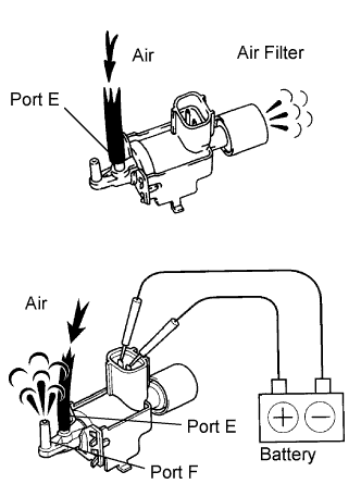
| 4.INSPECT VACUUM SWITCHING VALVE (OPERATION) |
Check that air flows from port E to the air filter.
Apply positive (+) battery voltage across the terminals.
Check that air flows from port E to port F.
| | REPLACE VACUUM SWITCHING VALVE |
|
|
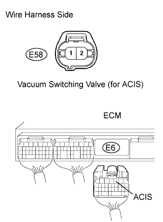
| 5.CHECK WIRE HARNESS (VACUUM SWITCHING VALVE - ECM, VACUUM SWITCHING VALVE) |
Disconnect the E58 vacuum switching valve (for ACIS) connector.
Disconnect the E6 ECM connector.
Measure the resistance of the wire harness side connectors.
- Standard resistance:
Tester Connection
| Specified Condition
|
E58-2 - E6-3 (ACIS)
| Below 1 Ω
|
E58-2 or E6-3 (ACIS) - Body ground
| 10 kΩ or higher
|
| | REPAIR OR REPLACE HARNESS AND CONNECTOR |
|
|
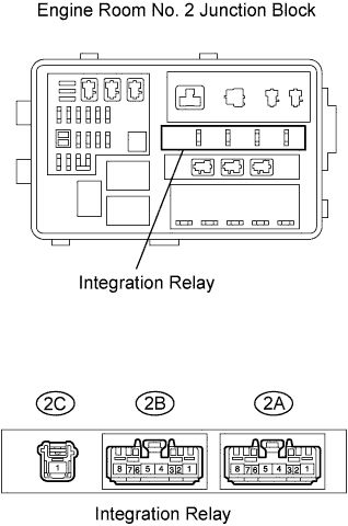
| 6.INSPECT INTEGRATION RELAY (EFI MAIN RELAY) |
Remove the integration relay from the engine room No. 2 junction block.
Measure the resistance of the EFI MAIN relay.
- Standard resistance:
Terminal Connections
| Specified Condition
|
2A-8 - 2C-1
| 10 kΩ or higher
|
2A-8 - 2C-1
| Below 1 Ω
(when battery voltage is applied to terminals 2A-6 and 2A-7)
|
| | REPLACE INTEGRATION RELAY |
|
|