Electronic Controlled Automatic Transmission System Pattern Select Switch Snow Mode Circuit
DESCRIPTION
WIRING DIAGRAM
INSPECTION PROCEDURE
DRIVING TEST
CHECK HARNESS AND CONNECTOR (PATTERN SELECT SWITCH ASSEMBLY - BODY GROUND)
INSPECT PATTERN SELECT SWITCH ASSEMBLY
CHECK HARNESS AND CONNECTOR
ELECTRONIC CONTROLLED AUTOMATIC TRANSMISSION SYSTEM - Pattern Select Switch Snow Mode Circuit |
DESCRIPTION
Cowl side J/B ECU receives pattern select switch information, and sends it through the multiplex communication system and CAN system to the ECM.ECT SNOW is the system that operates the throttle motor to control engine output to reduce skidding of the driving wheels, guarantee takeoff acceleration, driving straightness and turning stability.
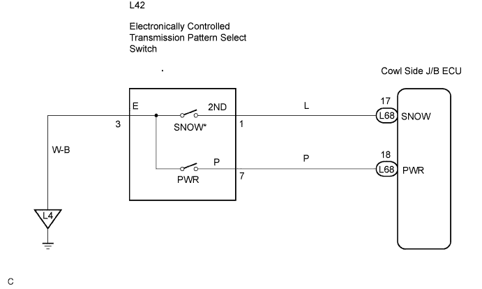
WIRING DIAGRAM
- HINT:
- (*) Pattern Select Switch (ECT SNOW Switch)
- When the ECT SNOW switch is pushed, the switch contact is made and the ECT SNOW mode is selected.
- To cancel the ECT SNOW mode, push the ECT SNOW switch once again.
- The ECT SNOW mode is automatically cancelled out when the engine switch is turned "OFF".
INSPECTION PROCEDURE
Start the engine.
Turn the ECT SNOW switch "OFF" (Normal drive mode).
Confirm vehicle response by driving from a parked position to fully depressing the accelerator pedal.
Turn the ECT SNOW switch "ON" and perform the same check as above.
Confirm that there is a difference between ECT SNOW switch "ON" and "OFF".
- HINT:
- Driving test should be done on a paved road (a nonskid road).
- Make sure not to use the TRAC system when testing a vehicle equipped with one.
- OK:
- There is a difference in acceleration between "ON" and "OFF".
| OK |
|
|
|
| PROCEED TO NEXT CIRCUIT INSPECTION SHOWN IN PROBLEM SYMPTOM TABLE |
|
| 2.CHECK HARNESS AND CONNECTOR (PATTERN SELECT SWITCH ASSEMBLY - BODY GROUND) |
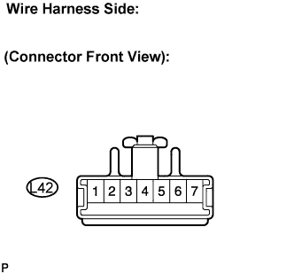
Disconnect the connector of pattern select switch.
Measure the resistance according to the value(s) in the table below.
- Resistance:
Tester Connection
| Specified Condition
|
3 - Body ground
| Below 1 Ω
|
| | REPAIR OR REPLACE HARNESS OR CONNECTOR |
|
|
| 3.INSPECT PATTERN SELECT SWITCH ASSEMBLY |
Measure the resistance according to the value(s) in the table below.
- Resistance:
Switch Condition
| Tester Connection
| Specified Condition
|
Press continuously Pattern select switch
(SNOW)
| 1 - 3
| Below 1 Ω
|
Release Pattern select switch
(SNOW)
| ↑
| 10 kΩ or higher
|
| | REPLACE PATTERN SELECT SWITCH ASSEMBLY |
|
|
| 4.CHECK HARNESS AND CONNECTOR |
Connect the connector of pattern select switch.
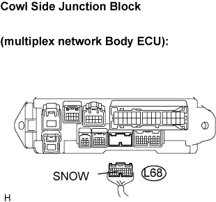
Disconnect the cowl side junction block (multiplex network body ECU) connector.
Measure the resistance between terminal SNOW of the cowl side junction block (multiplex network body ECU) and body ground.
- Resistance:
Switch Condition
| Tester Connection
| Specified Condition
|
Press continuously Pattern select switch
(SNOW)
| L68 - 17 (SNOW) - Body ground
| Below 1 Ω
|
Release Pattern select switch
(SNOW)
| ↑
| 10 kΩ or higher
|
| | REPAIR OR REPLACE HARNESS OR CONNECTOR |
|
|
| OK |
|
|
|
| PROCEED TO NEXT CIRCUIT INSPECTION SHOWN IN PROBLEM SYMPTOM TABLE |
|