Entry And Start System Engine Does Not Start
Engine. Lexus Gs430, Gs300. Uzs190 Grs190
DESCRIPTION
WIRING DIAGRAM
INSPECTION PROCEDURE
CHECK FOR DTC
CHECK BASIC FUNCTION
CHECK SWITCH CONDITION
CHECK BASIC FUNCTION
CHECK STEERING LOCK SYSTEM
CHECK WIRE HARNESS (POWER SOURCE CONTROL ECU - PNP SWITCH)
CHECK WIRE HARNESS (ENGINE ROOM NO. 2 RELAY BLOCK - POWER SOURCE CONTROL ECU)
CHECK POWER SOURCE CONTROL ECU
ENTRY AND START SYSTEM - Engine does not Start |
DESCRIPTION
| ENGINE START SYSTEM OPERATION |
If the engine switch is pressed with the shift lever in P or N and the brake pedal depressed, the power source control ECU determines that it is an engine start request.
The certification ECU and other ECUs perform key verification via the LIN communication line.
The power source control ECU activates the ACC relay.
The power source control ECU activates the IG1, IG2, and ST CUT relays. The engine switch indicator light illuminates green.
The certification ECU outputs a steering UNLOCK signal. The signal is sent to the steering lock ECU via the power source control ECU.
The power source control ECU sends an engine start request signal to the ECM.
The ECM and power source control ECU activate the ST relay.
The ECM sends an ACC relay cut signal to the power source control ECU.
The power source control ECU deactivates the ACC relay until the ECU detects an engine start request.
When engine revolution speed reaches 800 rpm, the power source control ECU determines that the engine has been started. The ECU reactivates the ACC relay and turns off the engine switch indicator light.
Symbols of power source control ECU
| Signals
|
STP
| Stop light switch ON signal
|
SSW1/SSW2
| Engine switch ON signal
|
ACCD
| ACC relay operation signal
|
IG2D
| IG2 relay operation signal
|
STR2
| ST relay operation signal
|
STR1
| Park/neutral position switch signal
|
TACH
| Engine start detection signal
|
STSW
| Starter activation request signal
|
CTSW
| Start assist signal
|
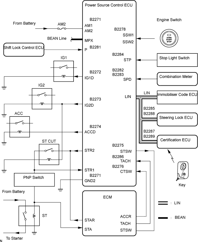
WIRING DIAGRAM
See CRANKING HOLDING FUNCTION CIRCUIT (Click here).
INSPECTION PROCEDURE
Delete the DTCs.
- HINT:
- After all DTCs are cleared, check if the trouble occurs again 5 seconds after the engine switch is turned on (IG).
Check for DTCs again.
- OK:
- No DTC is output.
When there is fuel in the fuel tank, the key is inside the vehicle and the shift lever is on P, check that depressing the brake pedal causes the engine to start.
- OK:
- Engine starts.
When the key is inside the vehicle and the shift lever is on P, check that depressing the brake pedal while pressing the engine switch causes the power source mode to change as follows.
- OK:
- off → on (ACC) → on (IG) → off
| | GO TO POWER SOURCE MODE DOES NOT CHANGE |
|
|
When there is fuel in the fuel tank, the key is inside the vehicle and the shift lever is on P, check that depressing the brake pedal and pressing the engine switch cranks the engine.
- OK:
- Engine cranks.
| OK |
|
|
|
| GO TO ENGINE IMMOBILISER SYSTEM |
|
| 5.CHECK STEERING LOCK SYSTEM |
When the engine switch is on (ACC), check that the steering lock can be released.
- OK:
- Steering lock can be released.
| | GO TO STEERING LOCK SYSTEM |
|
|
| 6.CHECK WIRE HARNESS (POWER SOURCE CONTROL ECU - PNP SWITCH) |
Disconnect the L73 ECU connector.
Disconnect the E25 switch connector.
Measure the resistance of the wire harness side connectors.
- Standard resistance:
Tester Connection
| Specified Condition
|
L73-17 (STR1) - E25-9
| Below 1 Ω
|
L73-17 (STR1) or E25-9 - Body ground
| 10 kΩ or higher
|
| | REPAIR OR REPLACE HARNESS AND CONNECTOR |
|
|
| 7.CHECK WIRE HARNESS (ENGINE ROOM NO. 2 RELAY BLOCK - POWER SOURCE CONTROL ECU) |
Remove the ST CUT relay from the engine room No. 2 relay block.
Disconnect the L73 ECU connector.
Measure the resistance of the wire harness side connectors.
- Standard resistance:
Tester Connection
| Specified Condition
|
Engine room No. 2 relay block ST CUT relay terminal 3 - L73-15 (STR2)
| Below 1 Ω
|
Engine room No. 2 relay block ST CUT relay terminal 3 or L73-15 (STR2) - Body ground
| 10 kΩ or higher
|
- Standard resistance:
Tester Connection
| Specified Condition
|
Engine room No. 2 relay block ST CUT relay terminal 2- L73-35 (IG2D)
| Below 1 Ω
|
Engine room No. 2 relay block ST CUT relay terminal 2 or L73-35 (IG2D) - Body ground
| 10 kΩ or higher
|
| | REPAIR OR REPLACE HARNESS AND CONNECTOR |
|
|
| 8.CHECK POWER SOURCE CONTROL ECU |
Reconnect the L73 ECU connector.
Measure the voltage of the ECU.
- Standard voltage:
Tester Connection
| Condition
| Specified Condition
|
L73-39 (STSW) - Body ground
| Engine switch on (IG)
| 10 to 14 V
|
| | REPAIR OR REPLACE HARNESS AND CONNECTOR |
|
|