Air Conditioning System Ptc Heater Circuit
DESCRIPTION
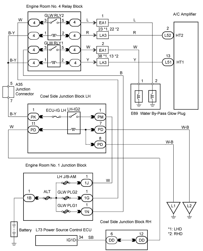
WIRING DIAGRAM
INSPECTION PROCEDURE
INSPECT FUSE (ECU-IG LH, GLW PLG1, GLW PLG2)
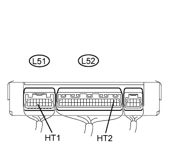
CHECK AIR CONDITIONING AMPLIFIER
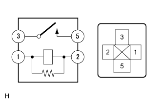
INSPECT RELAY (GLW RLY1, GLW RLY2)
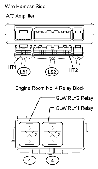
CHECK WIRE HARNESS (A/C AMPLIFIER - ENGINE ROOM NO. 4 RELAY BLOCK)
INSPECT WATER BY-PASS GLOW PLUG
INSPECT HEATER BLOWER WIRE
CHECK WIRE HARNESS (HEATER BLOWER WIRE - ENGINE ROOM NO. 4 RELAY BLOCK)
AIR CONDITIONING SYSTEM - PTC Heater Circuit |
DESCRIPTION
The GLW RLY turns on when it receives a signal from the A/C amplifier. As a result, power is supplied to the heater glow plug.
WIRING DIAGRAM
INSPECTION PROCEDURE
| 1.INSPECT FUSE (ECU-IG LH, GLW PLG1, GLW PLG2) |
Remove the ECU-IG LH fuse from the cowl side junction block LH.
Remove the GLW PLG1 and GLW PLG2 H-fuses from the engine room No. 1 junction block.
Measure the resistance of the fuses.
- Standard resistance:
Tester Item
| Condition
| Specified Condition
|
ECU-IG LH fuse
| Always
| Below 1 Ω
|
GLW PLG1 H-fuse
| Always
| Below 1 Ω
|
GLW PLG2 H-fuse
| Always
| Below 1 Ω
|
| 2.CHECK AIR CONDITIONING AMPLIFIER |
Remove the A/C amplifier with its connectors still connected.
Turn the engine switch on (IG).
While the PTC operating conditions are met (engine is running at 850 rpm or more, ambient temperature is 3°C (37.4°F) or less, engine coolant temperature is 75°C (167°F) or less, A/C switch setting is MAX HOT), turn the blower switch to the Lo setting.
Measure the voltage of the connectors.
- Standard voltage:
Tester Connection
| Specified Condition
|
L52-2 (HT2) - Body ground
| 10 to 14 V
|
L52-1 (HT1) - Body ground
| 10 to 14 V
|
| | REPLACE AIR CONDITIONING AMPLIFIER |
|
|
| 3.INSPECT RELAY (GLW RLY1, GLW RLY2) |
Remove the GLW RLY1 and GLW RLY2 relays from the engine room No. 4 relay block.
Measure the resistance of the relays.
- Standard resistance:
Tester Connection
| Specified Condition
|
3 - 5
| 10 kΩ or higher
|
3 - 5
| Below 1 Ω
(when battery voltage is applied to terminals 1 and 2)
|
| 4.CHECK WIRE HARNESS (A/C AMPLIFIER - ENGINE ROOM NO. 4 RELAY BLOCK) |
Disconnect the L51 and L52 A/C amplifier connectors.
Remove the GLW RLY1 and GLW RLY2 relays from the engine room No. 4 relay block.
Measure the resistance of the wire harness side connectors.
- Standard resistance:
Tester Connection
| Specified Condition
|
L51-13 (HT1) - Relay block GLW RLY1 relay terminal 2
| Below 1 Ω
|
L52-2 (HT2) - Relay block GLW RLY2 relay terminal 2
| Below 1 Ω
|
| | REPAIR OR REPLACE HARNESS AND CONNECTOR |
|
|
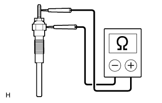
| 5.INSPECT WATER BY-PASS GLOW PLUG |
Remove the glow plug.
Measure the resistance of the glow plug.
- Standard resistance:
- Below 1 Ω
| | REPLACE WATER BY-PASS GLOW PLUG |
|
|
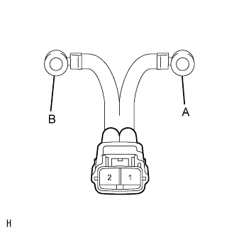
| 6.INSPECT HEATER BLOWER WIRE |
Remove the heater blower wire.
Measure the resistance of the blower wire.
- Standard resistance:
Tester Connection
| Condition
| Specified Condition
|
1 - A
| Always
| Below 1 Ω
|
1 - B
| Always
| 10 kΩ or higher
|
2 - B
| Always
| Below 1 Ω
|
2 - A
| Always
| 10 kΩ or higher
|
| | REPLACE HEATER BLOWER WIRE |
|
|
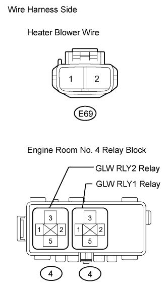
| 7.CHECK WIRE HARNESS (HEATER BLOWER WIRE - ENGINE ROOM NO. 4 RELAY BLOCK) |
Disconnect the E69 heater blower wire.
Remove the GLW RLY1 and GLW RLY2 relays from the engine room No. 4 relay block.
Measure the resistance of the wire harness side connectors.
- Standard resistance:
Tester Connection
| Specified Condition
|
Relay block GLW RLY1 relay terminal 5 - E69-1
| Below 1 Ω
|
Relay block GLW RLY2 relay terminal 5 - E69-2
| Below 1 Ω
|
| | REPAIR OR REPLACE HARNESS AND CONNECTOR |
|
|
| OK |
|
|
|
| PROCEED TO NEXT CIRCUIT INSPECTION SHOWN IN PROBLEM SYMPTOMS TABLE |
|