Electronic Power Steering System Terminals Of Ecu
Steering. Lexus Gs430, Gs300. Uzs190 Grs190
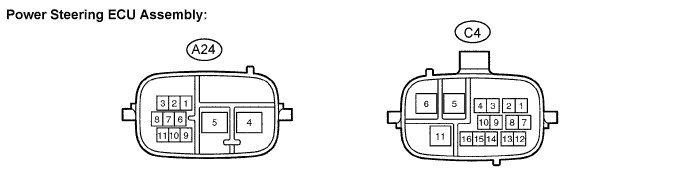
TERMINALS OF ECU
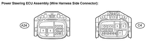
INSPECT WIRE HARNESS SIDE CONNECTOR
Electronic Power Steering System -- Terminals Of Ecu |
- HINT:
- The power steering ECU assembly uses waterproof connectors. Therefore, voltage or waveforms cannot be checked with the connectors connected to the vehicle.
Terminal No. (Symbols)
| Wiring Color
| Terminal Description
|
A24-1 (CAN+) (*1)
| B
| Local CAN communication
|
A24-2 (CANH)
| B
| High-level CAN bus line
|
A24-3 (CANL)
| W
| Low-level CAN bus line
|
A24-4 (PIG)
| W
| Power source
|
A24-5 (PGND)
| B
| Power ground
|
A24-8 (CAN-)
| W
| Local CAN communication
|
A24-9 (IG)
| B-Y
| IG power source
|
A24-10 (SIL)
| R
| Diagnosis communication signal
|
A24-11 (RLY)
| LG-B
| EPS relay drive signal
|
C4-1 (TRQV)
| W
| Torque sensor power source
|
C4-2 (RZV)
| B
| Rotation angle sensor power source
|
C4-3 (RZCS)
| R
| COS phase input signal (Rotation angle sensor)
|
C4-4 (RZSN)
| W
| SIN phase input signal (Rotation angle sensor)
|
C4-5 (U)
| B
| U phase motor output
|
C4-6 (W)
| R
| W phase motor output
|
C4-7 (INSN)
| G-W
| SIN phase input signal (torque sensor input shaft side)
|
C4-8 (INCS)
| R-L
| COS phase input signal (torque sensor input shaft side)
|
C4-9 (OUSN)
| G-B
| SIN phase input signal (torque sensor output shaft side)
|
C4-10 (OUCS)
| Y-B
| COS phase input signal (torque sensor output shaft side)
|
C4-11 (V)
| W
| V phase motor output
|
C4-12 (TQG1)
| L-W
| Torque sensor power source circuit ground
|
C4-13 (RZG)
| G
| Rotation angle sensor power source circuit ground
|
C4-14 (TQG2)
| R-B
| Torque sensor detection circuit ground
|
C4-15 (SRZG)
| BR
| Rotation angle sensor shield ground
|
- *1: 3UZ-FE
| INSPECT WIRE HARNESS SIDE CONNECTOR |
Terminal No. (Symbols)
| Wiring Color
| Terminal Description
| Condition
| Specified Condition
|
A24-4 (PIG) - A24-5 (PGND)
| W-B
| Power source
| Always
| Below 1 V
|
A24-5 (PGND) - Body ground
| B - Body ground
| Power ground
| Always
| Below 1 Ω
|
A24-9 (IG) - A24-5 (PGND)
| B-Y - B
| IG power source
| Engine switch on (IG)
| 10 to 14 V
|
A24-11 (RLY) - A24-5 (PGND)
| LG-B - B
| EPS relay drive signal
| Always
| 10 to 14 V
|
C4-5 (U) - C4-6 (W)/C4-11 (V)
| B - R/W
| U phase motor output
| Always
| Below 1 Ω
|
C4-6 (W) - C4-5 (U)/C4-11 (V)
| R - B/W
| W phase motor output
| Always
| Below 1 Ω
|
C4-11 (V) - C4-5 (U)/ C4-6 (W)
| W - B/R
| V phase motor output
| Always
| Below 1 Ω
|