Dtc B1217 Rear Door Ecu Lh Communication Stop
DESCRIPTION
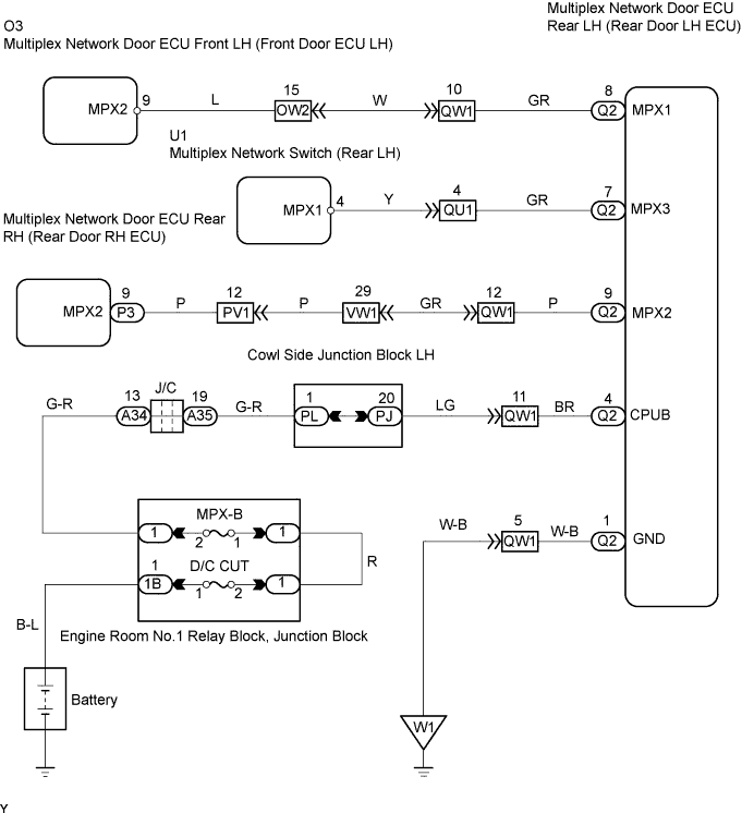
WIRING DIAGRAM
INSPECTION PROCEDURE
CHECK OPERATION
CHECK WIRE HARNESS (MULTIPLEX NETWORK DOOR ECU REAR LH (REAR DOOR LH ECU) - BATTERY AND BODY GROUND)
CHECK RESISTANCE OF COMMUNICATION LINE
DTC B1217 Rear Door ECU LH Communication Stop |
DESCRIPTION
- This DTC is detected when communication between the multiplex network door ECU rear LH (rear door LH ECU) and gateway ECU stops for more than 10 seconds.
DTC No.
| DTC Detection Condition
| Trouble Area
|
B1217
| Rear door LH ECU communication stops
| - Multiplex network door ECU rear LH (rear door LH ECU)
- Wire harness
|
WIRING DIAGRAM
INSPECTION PROCEDURE
Open the rear door LH and check that the door warning light (built into combination meter) illuminates.
- OK:
- Door warning light illuminates.
| OK |
|
|
|
| REPLACE MULTIPLEX NETWORK DOOR ECU REAR LH (REAR DOOR LH ECU) |
|
| 2.CHECK WIRE HARNESS (MULTIPLEX NETWORK DOOR ECU REAR LH (REAR DOOR LH ECU) - BATTERY AND BODY GROUND) |
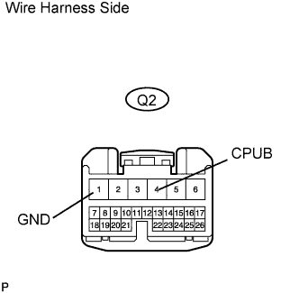
Disconnect the Q2 ECU connector.
Measure the resistance and voltage of the wire harness side connector.
- Standard voltage:
Tester Connection
| Specified Condition
|
Q2-4 (CPUB) - Body ground
| 10 to 14 V
|
- Standard resistance:
Tester Connection
| Specified Condition
|
Q2-1 (GND) - Body ground
| Below 1 Ω
|
| | REPAIR OR REPLACE HARNESS AND CONNECTOR |
|
|
| 3.CHECK RESISTANCE OF COMMUNICATION LINE |
Disconnect the Q2, O3, U1 and P3 ECU connectors.
Measure the resistance of the wire harness side connectors.
- Standard resistance:
Tester Connection
| Specified Condition
|
Q2-8 (MPX1) - O3-9 (MPX2)
| Below 1 Ω
|
Q2-7 (MPX3) - U1-4 (MPX1)
| Below 1 Ω
|
Q2-9 (MPX2) - P3-9 (MPX2)
| Below 1 Ω
|
- Result:
Result
| Proceed to
|
Both are OK
| A
|
One is OK
| B
|
Both are NG
| C
|
| | REPLACE MULTIPLEX NETWORK DOOR ECU REAR LH AND WIRE HARNESS CONNECTOR |
|
|
| | REPAIR OR REPLACE HARNESS AND CONNECTOR |
|
|
| A |
|
|
|
| REPLACE MULTIPLEX NETWORK DOOR ECU REAR LH (REAR DOOR LH ECU) |
|