Can Communication System Terminals Of Ecu
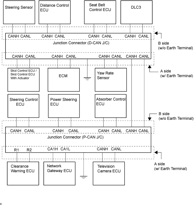
JUNCTION CONNECTOR (D-CAN J/C, P-CAN J/C), LHD.
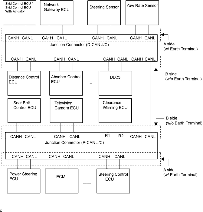
JUNCTION CONNECTOR (D-CAN J/C, P-CAN J/C), RHD.
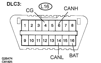
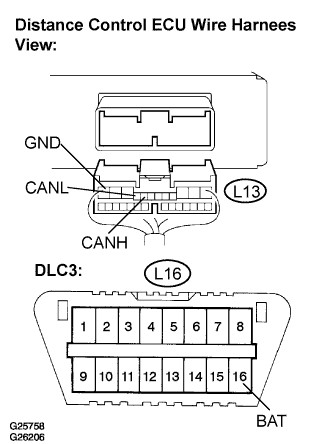
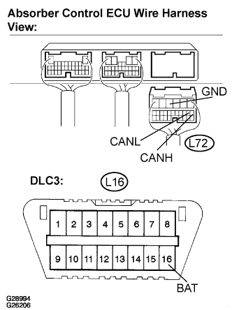
DLC3
SKID CONTROL ECU
SKID CONTROL ECU WITH ACTUATOR
STEERING SENSOR
YAW RATE SENSOR
DISTANCE CONTROL ECU
TELEVISION CAMERA ECU
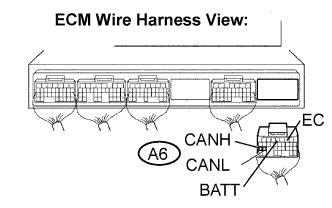
ECM
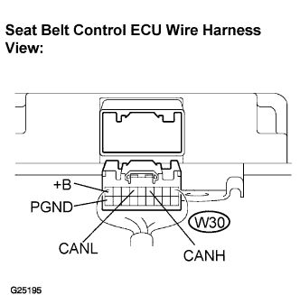
SEAT BELT CONTROL ECU
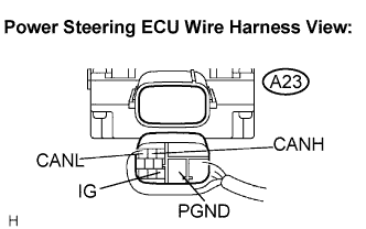
POWER STEERING ECU
STEERING CONTROL ECU
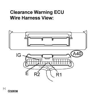
CLEARANCE WARNING ECU
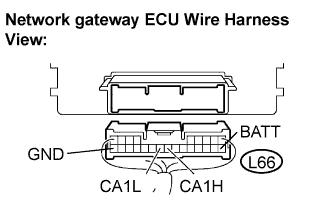
NETWORK GATEWAY ECU
ABSORBER CONTROL ECU
Can Communication System -- Terminals Of Ecu |
- NOTICE:
- This section describes the standard CAN values for all CAN related components.
| JUNCTION CONNECTOR (D-CAN J/C, P-CAN J/C), LHD. |
D-CAN J/C.
- Wiring color:
D-CAN J/C connectors (A side, w/ earth terminal)
| Color (CAN-H Side)
| Color (CAN-L Side)
|
Skid control ECU/ Skid control ECU with actuator
| P
| O
|
ECM
| BR
| GR
|
CAN main bus line (bus line to connect - D-CAN and P-CAN J/C )
| B
| W
|
Yaw rate sensor
| R
| W
|
- Wiring color:
D-CAN J/C connectors (B side, w/o earth terminal)
| Color (CAN-H Side)
| Color (CAN-L Side)
|
Distance control ECU
| BR
| Y
|
Seat belt control ECU
| P
| W
|
DLC3
| L
| LG
|
Steering angle sensor
| R
| W
|
- HINT:
- The connectors connected to the CAN J/C can be distinguished by the colors of the bus lines and the connecting side of the connector.
- The connectors can be connected to any terminals on the same side.
|
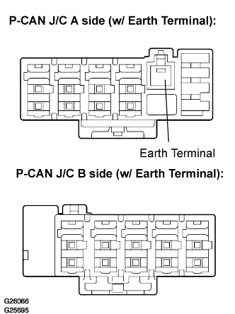
P-CAN J/C.
- Wiring color:
P-CAN J/C A Side (w/ Earth Terminal)
| Color (CAN-H Side)
| Color (CAN-L Side)
|
Clearance warning ECU
| P
| LG
|
Network gateway ECU
| L
| Y
|
Television camera ECU
| BR
| GR
|
- Wiring color:
P-CAN J/C B Side (w/o Earth Terminal)
| Color (CAN-H Side)
| Color (CAN-L Side)
|
CAN bus line (bus line connect P-CAN J/C and D-CAN J/C)
| B
| W
|
Steering control ECU
| R
| W
|
Absorber control ECU
| BR
| Y
|
Power steering ECU
| P
| V
|
- HINT:
- The connectors connected to the CAN J/C can be distinguished by the colors of the bus lines and the connecting side of the connector.
- The connectors can be connected to any terminals on the same side.
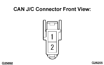
The terminals on connectors for the CAN J/C.
Terminal
| Terminal symbol
|
1
| CANH
|
1
| CANL
|
Wiring diagram for identifying CAN J/C connectors.
| JUNCTION CONNECTOR (D-CAN J/C, P-CAN J/C), RHD. |
D-CAN J/C.
- Wiring color:
D-CAN J/C connectors (A side, w/ earth terminal)
| Color (CAN-H Side)
| Color (CAN-L Side)
|
Skid control ECU/ Skid control ECU with actuator
| BR
| GR
|
Network gateway ECU
| L
| Y
|
Steering sensor
| R
| W
|
Yaw rate sensor
| P
| LG
|
- Wiring color:
D-CAN J/C connectors (B side, w/o earth terminal)
| Color (CAN-H Side)
| Color (CAN-L Side)
|
Distance control ECU
| P
| V
|
Absorber control ECU
| BR
| Y
|
DLC3
| L
| LG
|
CAN main bus line (bus line to connect - D-CAN and P-CAN J/C )
| B
| W
|
- HINT:
- The connectors connected to the CAN J/C can be distinguished by the colors of the bus lines and the connecting side of the connector.
- The connectors can be connected to any terminals on the same side.
|
P-CAN J/C.
- Wiring color:
P-CAN J/C A Side (w/ Earth Terminal)
| Color (CAN-H Side)
| Color (CAN-L Side)
|
Power steering ECU
| P
| O
|
ECM
| BR
| GR
|
Steering control ECU
| R
| W
|
- Wiring color:
P-CAN J/C B Side (w/o Earth Terminal)
| Color (CAN-H Side)
| Color (CAN-L Side)
|
Seat belt control ECU
| P
| W
|
Television camera ECU
| BR
| Y
|
Clearance warning ECU
| L
| Y
|
CAN bus line (bus line connect P-CAN J/C and D-CAN J/C)
| B
| W
|
- HINT:
- The connectors connected to the CAN J/C can be distinguished by the colors of the bus lines and the connecting side of the connector.
- The connectors can be connected to any terminals on the same side.
The terminals on connectors for the CAN J/C.
Terminal
| Terminal symbol
|
1
| CANH
|
1
| CANL
|
Wiring diagram for identifying CAN J/C connectors.
Measure the resistance according to the value(s) in the table below.
- Standard resistance:
Terminals
| Wiring Color
| Condition
| Specified Condition
|
L16-6 (CANH) - L16-14 (CANL)
| L - LG
| Engine Switch off
| 54 to 69 Ω
|
L16-6 (CANH) - L16-4 (CG)
| L - W-B
| Engine Switch off
| 1 kΩ or more
|
L16-14 (CANL) - L16-4 (CG)
| LG - W-B
| Engine Switch off
| 1 kΩ or more
|
L16-6 (CANH) - L16-16 (BAT)
| L - W-B
| Engine Switch off
| 1 MΩ or more
|
L16-14 (CANL) - L16-16 (BAT)
| LG - O
| Engine Switch off
| 1 MΩ or more
|
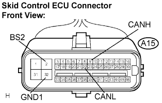
Measure the resistance according to the value(s) in the table below (3UZ-FE).
- Standard resistance:
Terminals
| Wiring Color
| Condition
| Specified Condition
|
A15-9 (CANH) - A15-25 (CANL)
| P - O
| Engine Switch off
| 54 to 69 Ω
|
A15-9 (CANH) - A15-32 (GND4)
| P - W-B
| Engine Switch off
| 1 kΩ or more
|
A15-22 (CANL) - A15-32 (GND4)
| O - W-B
| Engine Switch off
| 1 kΩ or more
|
A15-9 (CANH) - A15-2 (BS2)
| P - G
| Engine Switch off
| 1 MΩ or more
|
A15-22 (CANL) - A15-2 (BS2)
| O - G
| Engine Switch off
| 1 MΩ or more
|
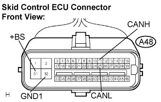
| SKID CONTROL ECU WITH ACTUATOR |
Measure the resistance according to the value(s) in the table below (3GR-FSE,3GR-FE).
- Standard resistance:
Terminals
| Wiring Color
| Condition
| Specified Condition
|
A48-11 (CANH) - A48-25 (CANL)
| P - O
| Engine Switch off
| 54 to 69 Ω
|
A48-11 (CANH) - A48-32 (GND1)
| P - W-B
| Engine Switch off
| 1 kΩ or more
|
A48-25 (CANL) - A48-32 (GND1)
| O - W-B
| Engine Switch off
| 1 kΩ or more
|
A48-11 (CANH) - A48-31 (+BS)
| P - R
| Engine Switch off
| 1 MΩ or more
|
A48-25 (CANL)- A48-32 (+BS)
| O - G
| Engine Switch off
| 1 MΩ or more
|
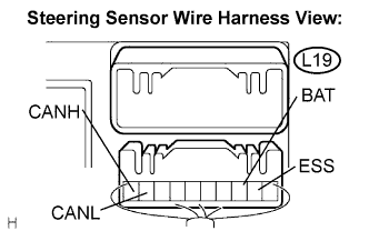
Measure the resistance according to the value(s) in the table below.
- Standard resistance:
Terminals
| Wiring Color
| Condition
| Specified Condition
|
L19-10 (CANH) - L19-9 (CANL)
| R - W
| Engine Switch off
| 54 to 69 Ω
|
L19-10 (CANH) - L19-2 (ESS)
| R - W-B
| Engine Switch off
| 1 kΩ or more
|
L19-9 (CANL) - L19-2 (ESS)
| W - W-B
| Engine Switch off
| 1 kΩ or more
|
L19-10 (CANH) - L19-3 (BAT)
| R - LG
| Engine Switch off
| 1 MΩ or more
|
L19-9 (CANL) - L19-3 (BAT)
| W - LG
| Engine Switch off
| 1 MΩ or more
|
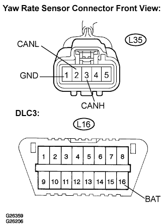
Measure the resistance according to the value(s) in the table below.
- Standard resistance:
Terminals
| Wiring Color
| Condition
| Specified Condition
|
L35-3 (CANH) - L35-2 (CANL)
| R - W
| Engine Switch off
| 54 to 69 Ω
|
L35-3 (CANH) - L35-1 (GND)
| R - W-B
| Engine Switch off
| 1 kΩ or more
|
L35-2 (CANL) - L35-1 (GND)
| W - W-B
| Engine Switch off
| 1 kΩ or more
|
L35-3 (CANH) - L16-16 (BAT)
| R - O
| Engine Switch off
| 1 MΩ or more
|
L35-2 (CANL) - L16-16 (BAT)
| W - O
| Engine Switch off
| 1 MΩ or more
|
Measure the resistance according to the value(s) in the table below.
- Standard resistance:
Terminals
| Wiring Color
| Condition
| Specified Condition
|
L13-8 (CANH) - L13-9 (CANL)
| BR - GR
| Engine Switch off
| 54 to 69 Ω
|
L13-8 (CANH) - L13-12 (GND)
| BR - G
| Engine Switch off
| 1 kΩ or more
|
L13-9 (CANL) - L13-12 (GND)
| GR - G
| Engine Switch off
| 1 kΩ or more
|
L13-8 (CANH) - L16-16 (BAT)
| BR - O
| Engine Switch off
| 1 MΩ or more
|
L13-9 (CANL) - L16-16 (BAT)
| GR - O
| Engine Switch off
| 1 MΩ or more
|
Measure the resistance according to the value(s) in the table below.
- Standard resistance:
Terminals
| Wiring Color (LHD)
| Wiring Color (RHD)
| Condition
| Specified Condition
|
L64-8 (CANH) - L64-7 (CANL)
| BR - GR
| BR - Y
| Engine Switch off
| 54 to 69 Ω
|
L64-8 (CANH) - L64-8 (GND1)
| BR - W-B
| BR - W-B
| Engine Switch off
| 1 kΩ or more
|
L64-7 (CANL) - L65-8 (GND1)
| GR - W-B
| Y - W-B
| Engine Switch off
| 1 kΩ or more
|
L64-8 (CANH) - L65-1 (+B)
| BR - L
| BR - L
| Engine Switch off
| 1 MΩ or more
|
L64-7 (CANL) - L65-1 (+B)
| GR - L
| Y - L
| Engine Switch off
| 1 MΩ or more
|
Measure the resistance according to the value(s) in the table below.
- Standard resistance:
Terminals
| Wiring Color
| Condition
| Specified Condition
|
A6-25 (CANH) - A6-24 (CANL)
| BR - GR
| Engine Switch off
| 54 to 69 Ω
|
A6-25 (CANH) - A6-2 (EC)
| BR - W-B
| Engine Switch off
| 1 kΩ or more
|
A6-24 (CANL) - A6-2 (EC)
| GR - W-B
| Engine Switch off
| 1 kΩ or more
|
A6-25 (CANH) - A6-4 (BATT)
| BR - L
| Engine Switch off
| 1 MΩ or more
|
A6-24 (CANL) - A6-4 (BATT)
| GR - L
| Engine Switch off
| 1 MΩ or more
|
Measure the resistance according to the value(s) in the table below.
- Standard resistance:
Terminals
| Wiring Color
| Condition
| Specified Condition
|
W30-4 (CANH) - W30-6 (CANL)
| P - W
| Engine Switch off
| 54 to 69 Ω
|
W30-4 (CANH) - W30-18 (PGND)
| P - W-B
| Engine Switch off
| 1 kΩ or more
|
W30-6 (CANL) - W30-18 (PGND)
| W - W-B
| Engine Switch off
| 1 kΩ or more
|
W30-4 (CANH) - W30-9 (+B)
| P - L
| Engine Switch off
| 1 MΩ or more
|
W30-6 (CANL) - W30-9 (+B)
| W - L
| Engine Switch off
| 1 MΩ or more
|
Measure the resistance according to the value(s) in the table below.
- Standard resistance:
Terminals
| Wiring Color (LHD)
| Wiring Color (RHD)
| Condition
| Specified Condition
|
A23-2 (CANH) - A23-3 (CANL)
| P - V
| P - O
| Engine Switch off
| 54 to 69 Ω
|
A23-2 (CANH) - A23-5 (PGND)
| P - B
| P - B
| Engine Switch off
| 1 kΩ or more
|
A23-3 (CANL) - A23-5 (PGND)
| V - B
| O - B
| Engine Switch off
| 1 kΩ or more
|
A23-2 (CANH) - A23-9 (IG)
| P - B-Y
| P - B-Y
| Engine Switch on (IG)
| 1 MΩ or more
|
A23-3 (CANL) - A23-9 (IG)
| V - B-Y
| P - B-Y
| Engine Switch on (IG)
| 1 MΩ or more
|
Measure the resistance according to the value(s) in the table below.
- Standard resistance:
Terminals
| Wiring Color
| Condition
| Specified Condition
|
L70-9 (CANH) - L70-20 (CANL)
| W - R
| Engine Switch off
| 54 to 69 Ω
|
L70-9 (CANH) - A42-7 (PGND)
| W - W-B
| Engine Switch off
| 1 kΩ or more
|
L70-20 (CANL) - A42-7 (PGND)
| R - W-B
| Engine Switch off
| 1 kΩ or more
|
L70-9 (CANH) - A42-10 (+B1)
| W - GR
| Engine Switch off
| 1 MΩ or more
|
L70-20 (CANL) - A42-10 (+B1)
| R - GR
| Engine Switch off
| 1 MΩ or more
|
Measure the resistance according to the value(s) in the table below.
- Standard resistance:
Terminals
| Wiring Color (LHD)
| Wiring Color (RHD)
| Condition
| Specified Condition
|
A40-23 (R1) - A40-24 (R2)
| P - LG
| L -Y
| Engine Switch off
| 54 to 69 Ω
|
A40-23 (R1) - A40-27 (E)
| P - W-B
| L - W-B
| Engine Switch off
| 1 kΩ or more
|
A40-24 (R2) - A40-27 (E)
| LG - W-B
| Y -W-B
| Engine Switch off
| 1 kΩ or more
|
A40-23 (R1) - A40-8 (IG)
| P - G-Y
| L - G-Y
| Engine Switch off
| 1 MΩ or more
|
A40-24 (R2) - A40-8 (IG)
| LG - G-Y
| Y - G-Y
| Engine Switch off
| 1 MΩ or more
|
Measure the resistance according to the value(s) in the table below.
- Standard resistance:
Terminals
| Wiring Color
| Condition
| Specified Condition
|
L66-17(CA1H)-L66-18(CA1L)
| L - Y
| Engine Switch off
| 54 to 69 Ω
|
L66-17 (CA1H) - L66-24 (GND)
| L - W-B
| Engine Switch off
| 1 kΩ or more
|
L66-18 (CA1L) - L66-24 (GND)
| Y - W-B
| Engine Switch off
| 1 kΩ or more
|
L66-17 (CA1H) - L66-10 (BATT)
| L- G
| Engine Switch off
| 1 MΩ or more
|
L66-18 (CA1L) - L66-10 (BATT)
| Y - G
| Engine Switch off
| 1 MΩ or more
|
Measure the resistance according to the value(s) in the table below.
- Standard resistance:
Terminals
| Wiring Color
| Condition
| Specified Condition
|
L72-7 (CANH) - L72-8 (CANL)
| R - Y
| Engine Switch off
| 54 to 69 Ω
|
L72-7 (CANH) - L72-4 (GND)
| R - W-B
| Engine Switch off
| 1 kΩ or more
|
L72-8 (CANL) - L72-4 (GND)
| Y - W-B
| Engine Switch off
| 1 kΩ or more
|
L72-7 (CANH) - L16-16 (BAT)
| R - L
| Engine Switch off
| 1 MΩ or more
|
L72-8 (CANL) - L16-16 (BAT)
| Y - L
| Engine Switch off
| 1 MΩ or more
|