Headlight Assembly Installation
Lighting. Lexus Gs430, Gs300. Uzs190 Grs190
INSTALL LIGHT CONTROL ECU
INSTALL FRONT SIDE MARKER LIGHT BULB SOCKET
INSTALL FRONT SIDE MARKER LIGHT BULB
INSTALL CLEARANCE LIGHT BULB SOCKET
INSTALL CLEARANCE LIGHT BULB
INSTALL FRONT TURN SIGNAL LIGHT BULB SOCKET
INSTALL FRONT TURN SIGNAL LIGHT BULB
INSTALL NO. 2 HEADLIGHT BULB
INSTALL HIGH-INTENSITY DISCHARGE HEADLIGHT BULB
INSTALL NO. 1 HEADLIGHT BACK COVER
INSTALL FRONT BUMPER SIDE SUPPORT
INSTALL HEADLIGHT ASSEMBLY
INSTALL ENGINE ROOM SIDE COVER
INSTALL FRONT BUMPER COVER
INSTALL COOL AIR INTAKE DUCT SEAL
CONNECT CABLE TO NEGATIVE BATTERY TERMINAL
PERFORM INITIALIZATION
HEADLIGHT AIMING ADJUSTMENT
VEHICLE PREPARATION FOR HEADLIGHT AIM ADJUSTMENT
PREPARATION FOR HEADLIGHT AIMING
HEADLIGHT AIMING INSPECTION
Headlight Assembly -- Installation |
- HINT:
- Use the same procedures for the RH side and LH side.
- The procedures listed below are for the LH side.
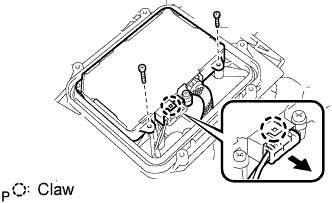
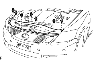
| 1. INSTALL LIGHT CONTROL ECU |
Attach the claw to install the ECU.
Install the 2 screws.
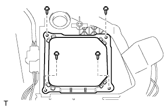
Install the cover with the 4 screws.
| 2. INSTALL FRONT SIDE MARKER LIGHT BULB SOCKET |
Install the bulb to the socket.
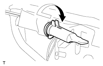
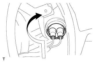
| 3. INSTALL FRONT SIDE MARKER LIGHT BULB |
Turn the socket and bulb in the direction indicated by the arrow and install them as a unit.
| 4. INSTALL CLEARANCE LIGHT BULB SOCKET |
Install the bulb to the socket.
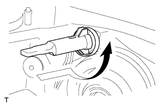
| 5. INSTALL CLEARANCE LIGHT BULB |
Turn the socket and bulb in the direction indicated by the arrow and install them as a unit.
| 6. INSTALL FRONT TURN SIGNAL LIGHT BULB SOCKET |
Install the bulb to the socket.
| 7. INSTALL FRONT TURN SIGNAL LIGHT BULB |
Turn the socket and bulb in the direction indicated by the arrow and install them as a unit.
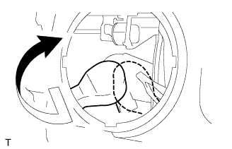
| 8. INSTALL NO. 2 HEADLIGHT BULB |
Turn the bulb in the direction indicated by the arrow and install it.
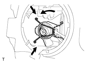
| 9. INSTALL HIGH-INTENSITY DISCHARGE HEADLIGHT BULB |
Hook the set spring lock to the groove to install it.
Turn the bulb in the direction indicated by the arrow and install the socket.
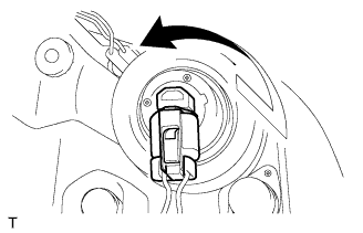
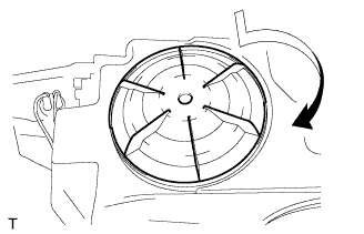
| 10. INSTALL NO. 1 HEADLIGHT BACK COVER |
Turn the back cover in the direction indicated by the arrow and install it.
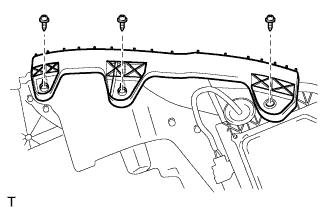
| 11. INSTALL FRONT BUMPER SIDE SUPPORT |
Install the side support with the 3 screws.
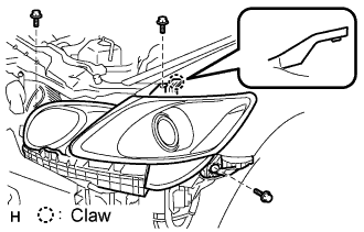
| 12. INSTALL HEADLIGHT ASSEMBLY |
Attach the claw and install the headlight with the 3 screws.
w/ Headlight cleaner:
Connect the hose.
Connect the connector as shown in the illustration.
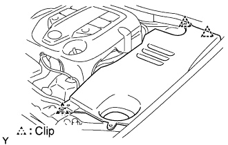
| 13. INSTALL ENGINE ROOM SIDE COVER |
Install the side cover with the 3 clips.
| 14. INSTALL FRONT BUMPER COVER |
Connect the ultrasonic sensor connector.
Attach the 3 claws on the LH side.
Attach the 3 claws on the RH side.
Install the bumper cover with the 2 clips, 6 screws and 5 bolts.
| 15. INSTALL COOL AIR INTAKE DUCT SEAL |
Install the duct seal with the 7 clips.
| 16. CONNECT CABLE TO NEGATIVE BATTERY TERMINAL |
| 17. PERFORM INITIALIZATION |
Perform initialization (Click here).
- NOTICE:
- Certain systems need to be initialized after disconnecting and reconnecting the cable from the negative (-) battery terminal.
| 18. HEADLIGHT AIMING ADJUSTMENT |
Adjust the aim vertically:
Adjust the headlight aim into the specified range by turning aiming screw A with a screwdriver.
- NOTICE:
- The final turn of the aiming screw should be made in the clockwise direction. If the screw is tightened excessively, loosen and then retighten it so that the final turn of the screw is in the clockwise direction.
- HINT:
- Perform the low-beam aim adjustment.
- The headlight aim moves up when turning the aiming screw clockwise, and moves down when turning the aiming screw counterclockwise.
Adjust the aim horizontally:
Adjust the headlight aim into the specified range by turning aiming screw B with a screwdriver.
- NOTICE:
- The final turn of the aiming screw should be made in the clockwise direction. If the screw is tightened excessively, loosen and then retighten it, so that the final turn of the screw is in the clockwise direction.
- HINT:
- Perform the low-beam aim adjustment.
| 19. VEHICLE PREPARATION FOR HEADLIGHT AIM ADJUSTMENT |
Adjust the aim vertically:
Adjust the headlight aim into the specified range by turning aiming screw A with a screwdriver.
- NOTICE:
- The final turn of the aiming screw should be made in the clockwise direction. If the screw is tightened excessively, loosen and then retighten it so that the final turn of the screw is in the clockwise direction.
- HINT:
- Perform the low-beam aim adjustment.
- The headlight aim moves up when turning the aiming screw clockwise, and moves down when turning the aiming screw counterclockwise.
Adjust the aim horizontally:
Adjust the headlight aim into the specified range by turning aiming screw B with a screwdriver.
- NOTICE:
- The final turn of the aiming screw should be made in the clockwise direction. If the screw is tightened excessively, loosen and then retighten it, so that the final turn of the screw is in the clockwise direction.
- HINT:
- Perform the low-beam aim adjustment.
| 20. PREPARATION FOR HEADLIGHT AIMING |
Prepare the vehicle according to the following conditions:
- Place the vehicle in a location that is dark enough to clearly observe the cutoff line.
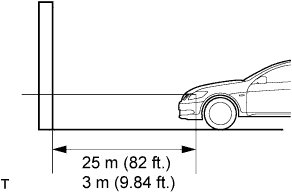
- Place the vehicle at a 90° angle to the wall.
- Create a 25 m (82 ft.) distance between the vehicle (headlight bulb center) and the wall.
- Place the vehicle on a level surface.
- Bounce the vehicle up and down to settle the suspension.
- NOTICE:
- A distance of 25 m (82 ft.) between the vehicle (headlight bulb center) and the wall is necessary for proper aim adjustment. If unavailable, secure a distance of exactly 3 m (9.84 ft.) for check and adjustment. (The target zone will change with the distance, so follow the instructions in the illustration.)
Prepare a piece of thick white paper (approximately 2 m (6.6 ft.) (height) x 4 m (13.1 ft.) (width)) to use as a screen.
Draw a vehicle center line down the center of the screen (V line).
- HINT:
- Stand the screen perpendicular to the ground.
- Align the V line on the screen with the center of the vehicle.
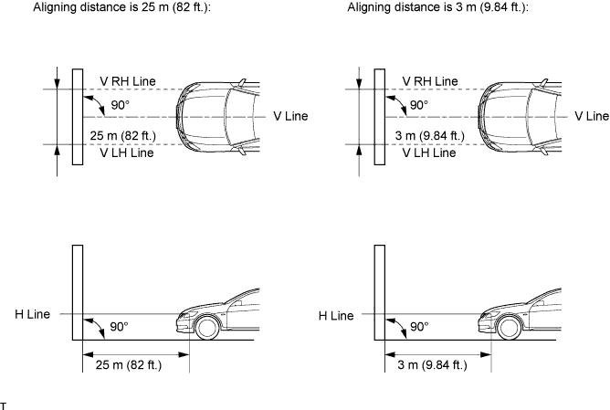
Set the screen as shown in the illustration.
Draw base lines (H line, V LH, V RH lines) on the screen as shown in the illustration.
- HINT:
- The base lines differ for ''low-beam inspection'' and ''high-beam inspection''.
- Mark the headlight bulb center marks on the screen. If the center mark cannot be observed on the headlight, use the center of the headlight bulb or the manufacturer's name marked on the headlight as the center mark.
H Line (Headlight height):
Draw a horizontal line across the screen so that it passes through the center marks. the H line should be at the same height as the headlight bulb center marks of the low-beam headlights.
V LH Line, V RH Line (Center mark position of left-hand (LH) and right-hand (RH) headlights):
Draw two vertical lines so that they intersect the H line at each center mark (aligned with the center of the low-beam headlight bulbs).
| 21. HEADLIGHT AIMING INSPECTION |
Cover or disconnect the connector of the headlight on the opposite side to prevent light from the head-light not being inspected from affecting the headlight aiming inspection.
- NOTICE:
- Do not keep the headlight covered for more than 3 minutes. The headlight lens is made of synthetic resin, and may easily melt or be damaged due to heat.
- HINT:
- When checking the aim of the high-beam, cover the low-beam or disconnect the connector.
Start the engine.
- NOTICE:
- Engine rpm must be 1,500 or more.
w/ headlight leveling switch:
Set the headlight leveling switch to 0 (zero).
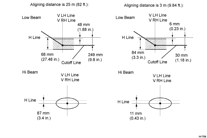
Turn on the headlight and make sure that the cutoff line falls within the specified area, as shown in the illustration.
- HINT:
- Alignment distance is 25 m (82 ft.):
The cutoff line is 48 mm (1.88 in.) to 698 mm (27.48 in.) below the H line with low-beam.
- Alignment distance is 3 m (9.84 ft.):
The cutoff line is 6 mm (0.23 in.) to 84 mm (3.3 in.) below the H line with low-beam.
- Alignment distance is 25 m (82 ft.):
The cutoff line is 249 mm (9.8 in.) below the H line with low-beam.
- Alignment distance is 3 m (9.84 ft.):
The cutoff line is 30 mm (1.88 in.) below the H line with low-beam.
- Since the low-beam light and the high-beam light are a unit, if the aim of either one is correct, the other should also be correct. However, check both beams just to make sure.