Variable Gear Ratio Steering System -- Check Mode Procedure |
| TEST MODE (VGRS SENSOR SIGNAL CHECK) |
- HINT:
When the system enters test mode, "VGRS TEST MODE" is displayed on the multi-information display.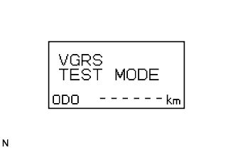
- Before entering test mode, check and repair any malfunctions indicated by the present DTCs of the VGRS system.
- By switching from normal mode to test mode, the steering angle sensor can be read.
- When entering test mode, the steering control ECU sets all the test mode DTCs first.
- When the mode is switched from test mode to normal mode, all the test mode DTCs will be erased.
Check the test mode DTCs (using the intelligent tester).
Turn the engine switch off.
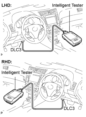
Connect the intelligent tester to the DLC3.
Turn the engine switch on (IG) and turn the intelligent tester on.
Read the test mode DTCs by following the prompts on the tester screen.
- HINT:
- Refer to the intelligent tester's operator's manual for further details.
Clear the test mode DTCs (using the intelligent tester).
Turn the engine switch off.
Connect the intelligent tester to the DLC3.
Turn the engine switch on (IG) and turn the intelligent tester on.
Switch the system from test mode to normal mode by following the directions on the tester screen.
- HINT:
- Refer to the intelligent tester's operator's manual for further details.
Check the test mode DTCs (using SST check wire).
Turn the engine switch off.
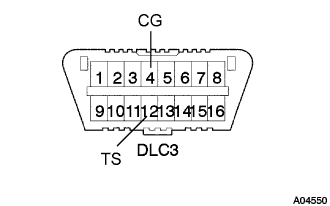
Using SST check wire, connect terminals TS (TC) and CG of the DLC3.
- SST
- 09843-18040
Turn the engine switch on (IG).
Read 2-digit test mode DTCs from the multi-information display.
- NOTICE:
- Perform these procedures with the vehicle stopped.
Clear the test mode DTCs (using SST check wire).
Turn the engine switch off.
Disconnect the SST check wire from the DLC3.
- SST
- 09843-18040
Turn the engine switch on (IG).
- HINT:
- If the engine switch is turned on (IG) with terminals TS and CG short-circuited, the system remains in test mode.
 |
|
| TEST MODE DTC |
If a trouble code is displayed during the DTC check, check the circuit indicated by the DTC. For details of each code, proceed to DTC chart.
DTC No. Detection Item Trouble Area C15C4/74 A steering signal indicating a tire angle of 36°or more (to the left or right) is input after transfer to test mode. (*1) - Steering angle sensor
- Steering control ECU
C15C5/75 A steering signal indicating a motor rotation angle of 36°or more (to the left or right) is input after transfer to test mode. (*1) - Steering angle sensor
- Steering control ECU
- HINT:
- *1: A tire angle of 36°and a motor rotation angle of 36°correspond to the steering wheel angle respectively. The amount of change in tire angle and motor rotation angle is from when the mode is changed to test mode.
- Steering angle sensor