Dtc B1296 Front Light Ecu Communication Stop
DESCRIPTION
WIRING DIAGRAM
INSPECTION PROCEDURE
CHECK OPERATION
INSPECT FUSE (MPX-B, D/C CUT)
CHECK WIRE HARNESS (ENGINE ROOM NO.2 R/B (FRONT CONTROLLER) - BATTERY AND BODY GROUND)
CHECK RESISTANCE OF COMMUNICATION LINE
CHECK OPERATION OF FRONT CONTROLLER
DTC B1296 Front Light ECU Communication Stop |
DESCRIPTION
This DTC is detected when communication between the engine room No. 2 junction block (front controller) and gateway ECU stops for more than 10 seconds.DTC No.
| DTC Detection Condition
| Trouble Area
|
B1296
| Front controller communication stops
| - Engine room No. 2 junction block (front controller)
- Wire harness
|
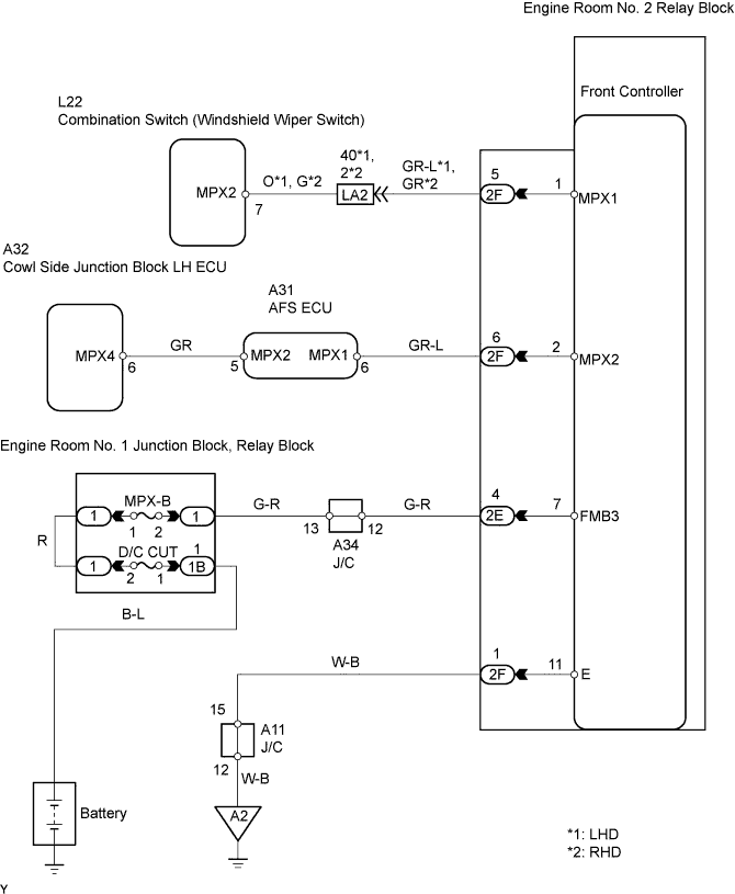
WIRING DIAGRAM
INSPECTION PROCEDURE
Turn the headlight dimmer switch ON and check that the headlights illuminate.
- OK:
- Headlights illuminate.
| OK |
|
|
|
| REPLACE ENGINE ROOM NO. 2 RELAY BLOCK (FRONT CONTROLLER) |
|
| 2.INSPECT FUSE (MPX-B, D/C CUT) |
Remove the MPX-B and D/C CUT fuses from the engine room No. 1 relay block, junction block.
Measure the resistance of the fuses.
- Standard resistance:
- Below 1 Ω
| 3.CHECK WIRE HARNESS (ENGINE ROOM NO.2 R/B (FRONT CONTROLLER) - BATTERY AND BODY GROUND) |
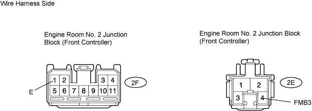
Disconnect the 2F and 2E relay block controllers from the engine room No. 2 relay block, junction block.
Measure the resistance of the wire harness side connectors.
- Standard voltage:
Tester Connection
| Specified Condition
|
2E-4 (FMB3) - Body ground
| 10 to 14 V
|
- Standard resistance:
Tester Connection
| Specified Condition
|
2F-1 (E) - Body ground
| Below 1 Ω
|
| | REPAIR OR REPLACE HARNESS AND CONNECTOR |
|
|
| 4.CHECK RESISTANCE OF COMMUNICATION LINE |
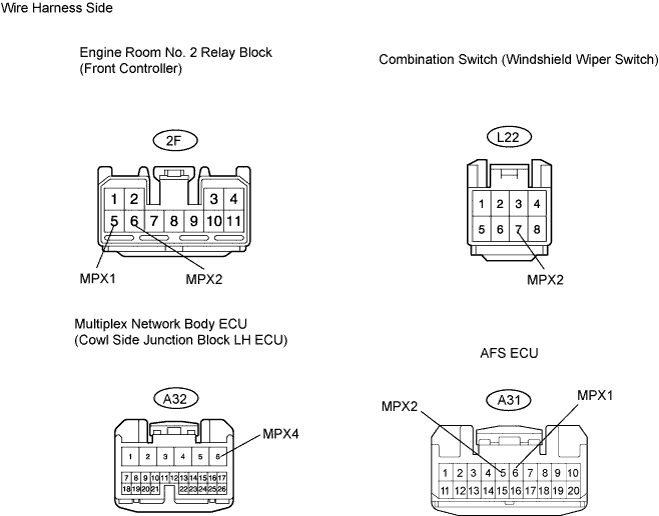
Disconnect the L22 switch connector.
Disconnect the A32 or A31 ECU connector.
Disconnect the 2F controller from the engine room relay block No. 2.
Measure the resistance of the wire harness side connectors.
- Standard resistance:
Tester Connection
| Specified Condition
|
2F-5 (MPX1) - L22-7 (MPX2)
| Below 1 Ω
|
2F-6 (MPX2) - A32-6 (MPX4)
| Below 1 Ω
|
2F-6 (MPX2) - A31-6 (MPX1)
| Below 1 Ω
|
- Result:
Result
| Proceed to
|
All are OK
| A
|
One or two is / are OK
| B
|
All are NG
| C
|
| | REPLACE ENGINE ROOM NO. 2 RELAY BLOCK AND HARNESS AND CONNECTOR |
|
|
| | REPAIR OR REPLACE HARNESS AND CONNECTOR |
|
|
| 5.CHECK OPERATION OF FRONT CONTROLLER |
After replacing the front controller with a normally functioning controller, check that the headlights illuminate.
- OK:
- Headlights illuminate.
| | REPLACE ENGINE ROOM NO. 2 RELAY BLOCK |
|
|