Dtc B1272 Power Seat Ecu Communication Stop
DESCRIPTION
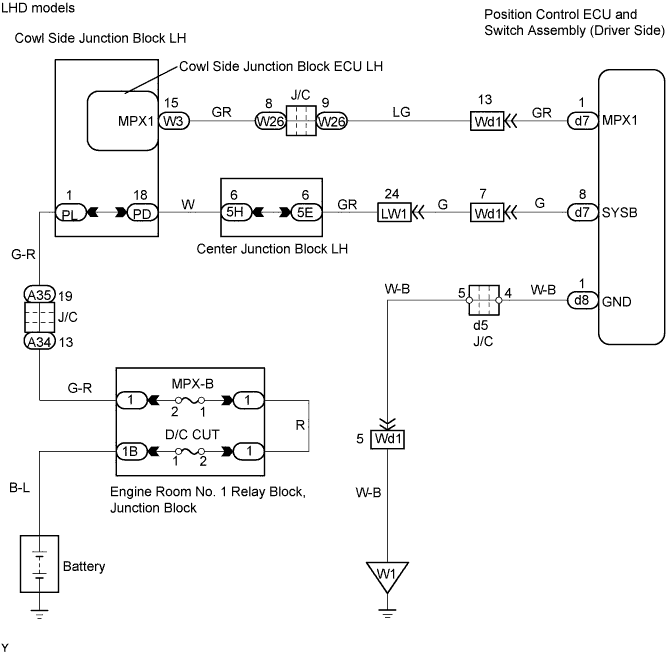
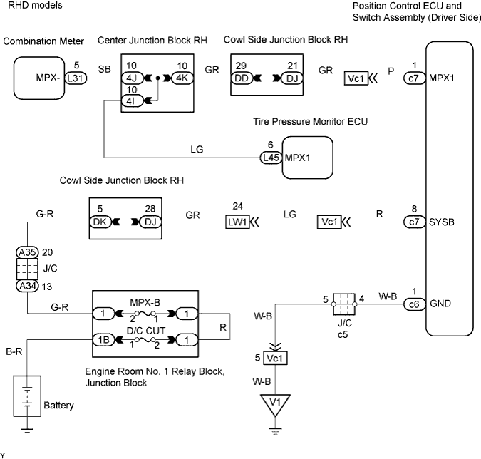
WIRING DIAGRAM
INSPECTION PROCEDURE
CHECK OPERATION
CHECK WIRE HARNESS (POSITION CONTROL ECU AND SWITCH ASSEMBLY (DRIVER SEAT ECU) - BATTERY AND BODY GROUND)
CHECK RESISTANCE OF COMMUNICATION LINE
DTC B1272 Power Seat ECU Communication Stop |
DESCRIPTION
This DTC is detected when communication between the position control ECU and switch (driver seat ECU) and network gateway ECU stops for more than 10 seconds.DTC No.
| DTC Detection Condition
| Trouble Area
|
B1272
| Position control ECU and switch assembly communication stops
| - Position control ECU and switch assembly (driver seat ECU)
- Wire harness
|
WIRING DIAGRAM
INSPECTION PROCEDURE
Check that the manual switch of the front power seat can move the driver side seat normally.
- OK:
- Manual switch of front power seat can move driver side seat normally.
| OK |
|
|
|
| REPLACE POSITION CONTROL ECU AND SWITCH ASSEMBLY (DRIVER SEAT ECU) |
|
| 2.CHECK WIRE HARNESS (POSITION CONTROL ECU AND SWITCH ASSEMBLY (DRIVER SEAT ECU) - BATTERY AND BODY GROUND) |
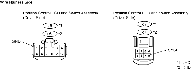
Disconnect the d8*1, c6*2 and d7*1, c7*2 ECU connectors.
Measure the resistance and voltage of the wire harness side connectors.
- Standard Resistance:
Tester Connection
| Specified Condition
|
d8-1 (GND)*1 - Body ground
| Below 1 Ω
|
c6-1 (GND)*2 - Body ground
| Below 1 Ω
|
- Standard Voltage:
Tester Connection
| Specified Condition
|
d7-8 (SYSB)*1 - Body ground
| 10 to 14 V
|
c7-8 (SYSB)*2 - Body ground
| 10 to 14 V
|
| | REPAIR OR REPLACE HARNESS AND CONNECTOR |
|
|
| 3.CHECK RESISTANCE OF COMMUNICATION LINE |
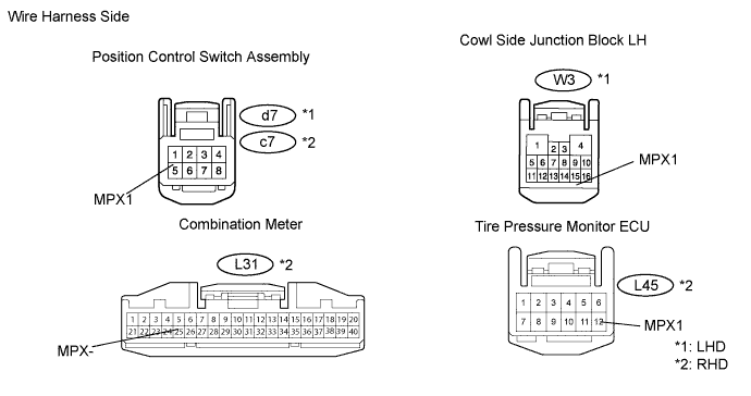
Disconnect the d7*1, c7*2 and W3*1, L31*2, L45*2 ECU connectors.
Measure the resistance of the wire harness side connectors.
- Standard resistance:
Tester Connection
| Specified Condition
|
d7-1 (MPX1)*1 - W3-15 (MPX1)*1
| Below 1 Ω
|
c7-1 (MPX1)*2 - L31-5 (MPX-)*2
| Below 1 Ω
|
c7-1 (MPX1)*2 - L45-6 (MPX1)*2
| Below 1 Ω
|
| | REPAIR OR REPLACE HARNESS AND CONNECTOR |
|
|
| OK |
|
|
|
| REPLACE POSITION CONTROL ECU AND SWITCH ASSEMBLY |
|