CHECK OTHER DTC OUTPUT (BESIDES DTC P0136, P0137, P0138, P0156, P0157 AND/OR P0158)
READ VALUE USING INTELLIGENT TESTER (OUTPUT VOLTAGE OF HEATED OXYGEN SENSOR)
INSPECT HEATED OXYGEN SENSOR (HEATER RESISTANCE)
INSPECT INTEGRATION RELAY (EFI MAIN RELAY)
CHECK HARNESS AND CONNECTOR (HEATED OXYGEN SENSOR - ECM)
PERFORM CONFIRMATION DRIVING PATTERN
READ OUTPUT DTC (DTC P0136 AND/OR P0156 ARE OUTPUT AGAIN)
DTC P0136 Oxygen Sensor Circuit Malfunction (Bank 1 Sensor 2) |
DTC P0137 Oxygen Sensor Circuit Low Voltage (Bank 1 Sensor 2) |
DTC P0138 Oxygen Sensor Circuit High Voltage (Bank 1 Sensor 2) |
DTC P0156 Oxygen Sensor Circuit Malfunction (Bank 2 Sensor 2) |
DTC P0157 Oxygen Sensor Circuit Low Voltage (Bank 2 Sensor 2) |
DTC P0158 Oxygen Sensor Circuit High Voltage (Bank 2 Sensor 2) |
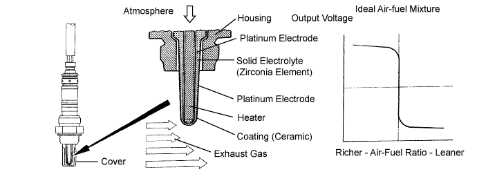
DESCRIPTION
- HINT:
- Sensor 2 refers to the sensor mounted behind the Three-Way Catalyst Converter (TWC) and located far from the engine assembly.
| DTC No. | DTC Detection Condition | Trouble Area |
| P0136 P0156 | During active control, heated oxygen sensor output voltage 0.2 to 0.6 V |
|
| P0136 P0156 | (a) and (b) are met for more than 90 seconds:
| |
| P0137 P0157 | During active control, heated oxygen sensor output voltage less than 0.2 V | |
| P0137 P0157 | (a) and (b) are met for more than 90 seconds:
| |
| P0138 P0158 | During active control, heated oxygen sensor output voltage more than 0.6 V | |
| P0138 P0158 | Rear oxygen sensor output voltage is 1.2 V or higher for more than 30 seconds |
- HINT:
- Bank 1 refers to the bank that includes cylinder No. 1.
- Bank 2 refers to the bank that does not include cylinder No. 1.
- Sensor 2 refers to the sensor farthest away from the engine assembly.
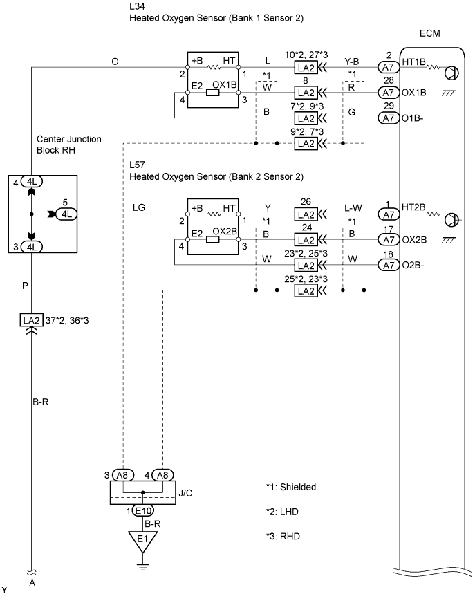
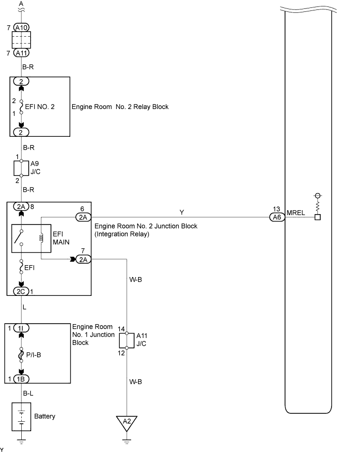
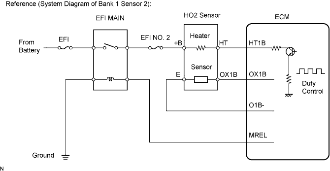
WIRING DIAGRAM
CONFIRMATION DRIVING PATTERN
- HINT:
- Performing this confirmation pattern will activate the DTC detection (P0136) of the ECM. This is very useful for verifying the completion of the repair.
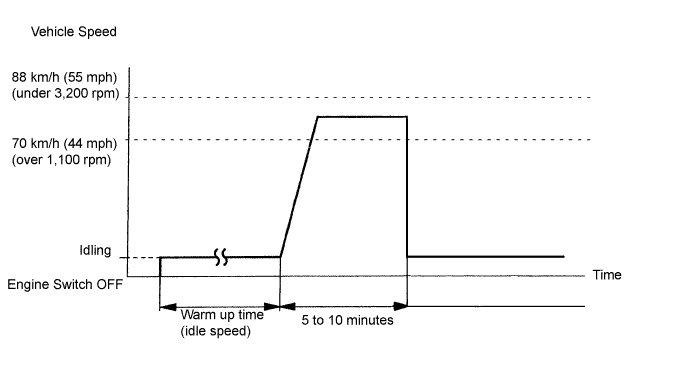
- (a) Clear the DTCs (Click here).
- (b) Switch the ECM From normal mode to check mode using the tester (Click here).
- (c) Start the engine and warm it up until the engine coolant temperature reaches more than 75°C (167°F).
- (d) Deactivate the inspection mode and drive the vehicle at 70 to 120 km/h (44 to 70 mph) for 5 to 10 minutes.
- (e) Read DTCs.
- NOTICE:
- If the conditions in this test are not strictly followed, no malfunction will be detected.
- Do not drive the vehicle without deactivating inspection mode. Otherwise damaging the transaxle may result.
INSPECTION PROCEDURE
- (a) Connect the intelligent tester to the DLC3.
- HINT:
- The malfunctioning areas can be found using the Active Test "Control the Injection Volume for A/F Sensor" operation. The Active Test can determine if the HO2S or other potential trouble areas are malfunctioning or not..
- (b) Turn the engine switch on (IG).
- (c) Warm up the engine with the engine speed at 2,500 rpm for approximately 90 seconds.
- (d) Enter the following menus: Powertrain / Engine / Active Test / Control the Injection Volume for A/F Sensor.
- (d) Perform the Active Test at the engine idling.
- Standard voltage:
- Heated oxygen sensor reaacts in accordance with increase and decrease of injection volume:
+25 % → rich output: More than 0.55 V
-12.5 % → lean output: Less than 0.4 V
- NOTICE:
- There is a few seconds delay in the A/F sensor output and there is about 20 seconds delay in the heated oxygen sensor output.
| Case | A/F Sensor (Sensor 1) Output Voltage | HO2 Sensor (Sensor 2) Output Voltage | Main Suspected Trouble Area | ||
| 1 | Injection Volume +25 % -12.5 % |  | Injection Volume +25 % -12.5 % | | - |
| Output Voltage More than 3.35 V Less than 3.0 V |  | Output Voltage More than 0.55 V Less than 0.4 V |  | ||
| 2 | Injection Volume +25 % -12.5 % | | Injection Volume +25 % -12.5 % | |
|
| Output Voltage Almost no reaction |  | Output Voltage More than 0.55 V Less than 0.4 V | | ||
| 3 | Injection Volume +25 % -12.5 % | | Injection Volume +25 % -12.5 % | |
|
| Output Voltage More than 3.35 V Less than 3.0 V | | Output Voltage Almost no reaction | | ||
| 4 | Injection volume +25 % -12.5 % | | Injection Volume +25 % -12.5 % | |
|
| Output Voltage Almost no reaction | | Output Voltage Almost no reaction | | ||
- HINT:
- Read freeze frame data using the intelligent tester. Freeze frame data records the engine conditions when malfunctions are detected. When troubleshooting, freeze frame data can help determine if the vehicle was running or stopped, if the engine was warmed up or not, if the air-fuel ratio was lean or rich, and other data from the time the malfunction occurred.
| 1.CHECK OTHER DTC OUTPUT (BESIDES DTC P0136, P0137, P0138, P0156, P0157 AND/OR P0158) |
Connect the intelligent tester to the DLC3.
Turn the engine switch on (IG) and turn the tester ON.
Enter the following menus: Powertrain / Engine / DTC.
Read DTCs.
Result: Display (DTC Output) Proceed to Only P0136, P0137, P0138, P0156, P0157 and/or P0158 are output A P0136, P0137, P0138, P0156, P0157 and/or P0158 and other DTCs are output B - HINT:
- If any other codes besides P0136, P0137, P0138, P0156, P0157 and/or P0158 are output, perform the troubleshooting for those DTCs first.
|
| ||||
| A | |
| 2.READ VALUE USING INTELLIGENT TESTER (OUTPUT VOLTAGE OF HEATED OXYGEN SENSOR) |
After warming up the engine, race the engine at 2,500 rpm for 3 minutes.
Read the output voltage of the heated oxygen sensor when the engine is suddenly raced.
- HINT:
- Perform a quick racing to 4,000 rpm 3 times by using the accelerator pedal.
- Standard voltage:
- Alternate 0.4 V or less and 0.5 V or more.
|
| ||||
| NG | |
| 3.INSPECT HEATED OXYGEN SENSOR (HEATER RESISTANCE) |
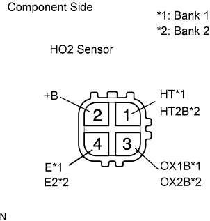 |
Disconnect the L34 or L57 HO2 sensor connector.
Measure the resistance.
- Standard resistance (Bank 1 Sensor 2):
Tester Connection Specified Condition HT (1) - +B (2) 11 to 16 Ω at 20°C (68°F) HT (1) - E (4) 10 kΩ or higher
- Standard resistance (Bank 2 Sensor 2):
Tester Connection Specified Condition HT2B (L57-1) - +B (L57-2) 11 to 16 Ω at 20°C (68°F) HT2B (L57-1) - E2 (L57-4) 10 kΩ or higher
|
| ||||
| OK | |
| 4.INSPECT FUSE (EFI NO. 2 FUSE) |
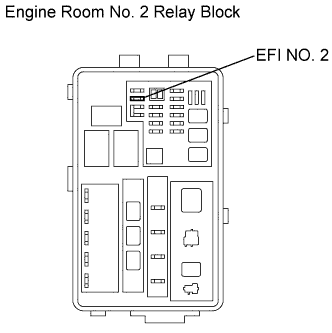 |
Remove the EFI NO. 2 fuse from the engine room No. 2 relay block.
Measure the resistance of the fuse.
- Standard resistance:
- Below 1 Ω
|
| ||||
| OK | |
| 5.INSPECT INTEGRATION RELAY (EFI MAIN RELAY) |
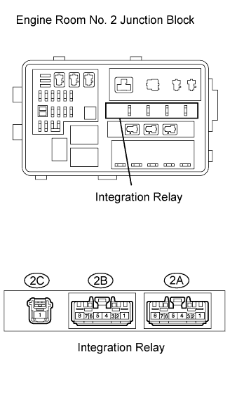 |
Remove the integration relay from the engine room No. 2 junction block.
Inspect the EFI MAIN relay.
- Standard resistance:
Tester Connection Specified Condition 2C-1 - 2A-8 10 kΩ or higher 2C-1 - 2A-8 Below 1 Ω
(Apply battery voltage between terminals 2C-1 and 2A-8
|
| ||||
| OK | |
| 6.CHECK HARNESS AND CONNECTOR (HEATED OXYGEN SENSOR - ECM) |
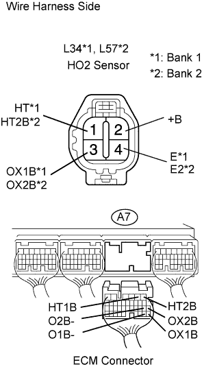  |
Disconnect the L34 and L57 heated oxygen sensor connectors.
Disconnect the A7 ECM connector.
Measure the resistance of the connectors.
- Standard resistance (Check for open):
Tester Connection Specified Condition OX1B (L34-3) - OX1B (A7-28) Below 1 Ω HT (L34-1) - HT1B (A7-2) Below 1 Ω E (L34-4) - O1B- (A7-29) Below 1 Ω OX2B (L57-3) - OX2B (A7-17) Below 1 Ω HT2B (L57-1) - HT2B (A7-1) Below 1 Ω E2 (L57-4) - O2B- (A7-18) Below 1 Ω
- Standard resistance (Check for short):
Tester Connection Specified Condition OX1B (L34-3) or OX1B (A7-28) - Body ground 10 kΩ or higher HT (L34-1) or HT1B (A7-2) - Body ground 10 kΩ or higher E (L34-4) or O1B- (A7-29) - Body ground 10 kΩ or higher OX2B (L57-3) or OX2B (A7-17) - Body ground 10 kΩ or higher HT2B (L57-1) or HT2B (A7-1) - Body ground 10 kΩ or higher E2 (L57-4) or O2B- (A7-18) - Body ground 10 kΩ or higher
|
| ||||
| OK | ||
| ||
| 7.PERFORM CONFIRMATION DRIVING PATTERN |
- HINT:
- Clear all DTCs prior to performing the confirmation driving pattern.
| NEXT | |
| 8.READ OUTPUT DTC (DTC P0136 AND/OR P0156 ARE OUTPUT AGAIN) |
Connect the intelligent tester to the DLC3.
Turn the engine switch on (IG) and turn the tester ON.
Enter the following menus: Powertrain / Engine / DTC.
Read DTCs.
Result: Display (DTC Output) Proceed to P0136 and/or P0156 are not output again A P0136 and/or P0156 are output again B
|
| ||||
| A | ||
| ||